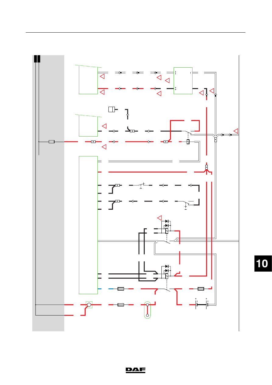
DAF LF45, LF55 Series. Manual - part 385
1
1427090/03
EL001557
54
55
56
57
58
59
60
61
62
63
64
65
66
67
68
69
70
71
72
73
74
75
76
77
78
79
80
81
82
83
84
85
86
87
88
89
90
91
92
93
94
95
96
97
98
99
100
101
102
103
104
105
106
1000
1000
1000
1000
1008
4176
3173
1167
1127
1167
BN
BW
BN
BW
1167
1167
1008
1167
1167
1167
4179
1167
4178
4178
4176
9036
4176
4174
4174
4175
4174
4175
4174
4175
4175
1009
1009
1167
1167
4176
9036
4176
4177
4177
4177
4177
4176
4179
4179
1123
9303
1123
9303
9001
4179
4179
1357
4179
1357
1357
1357
1357
1357
4178
A500
1/705
2/705
B525
A1/
752
A5/
752
D900
E1/
747
E349
80A
2
1
A3
718
4
822
A1
718
3
822
7
822
3
834
5
822
E330
5A
2
1
E153
10A
2
1
G367
88
88A
85A
85B
86
G368
88
88A
85A
85B
86
C853
5
71
0I
C854
1
2
!
!
!
!
!
!
!
!
!
!
!
A5
A7
C2
C5
C4
A2
C1
A3
A4
A1
D924
G425
30
85
86
87A
87
2
822
1
834
2
834
2
832
1
832
6
822
8
822
1
833
2
833
D826
+
4
2
3
1
831
4
902
2
831
3
A513
3
B6/702
D942
1000
1000
1010
1010
E143
10A
200440
2-29
5
ELECTRICAL SYSTEM
Electrical system
series
45/55
LF