DAF LF45, LF55 Series. Manual - part 384
1
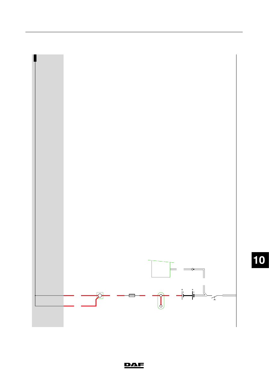
1427090/03
EL001558
123456789
1
0
1
1
1
2
1
3
1
4
1
5
1
6
1
7
1
8
1
9
2
0
2
1
2
2
2
3
2
4
2
5
2
6
2
7
2
8
2
9
3
0
3
1
3
2
3
3
3
4
3
5
3
6
3
7
3
8
3
9
4
0
4
1
4
2
4
3
4
4
4
5
4
6
4
7
4
8
4
9
5
0
5
1
5
2
5
3
1000
1000
1000
1000
9001
9001
1000
A500
1
813
1/705
2/705
B525
A5/
752
E349
80A
2
1
D942
1000
1000
G525
C553
2
1
200440
2-25
5
ELECTRICAL SYSTEM
Electrical system
series
45/55
LF