DAF LF45, LF55 Series. Manual - part 344


  Index      DAF     DAF LF45, LF55 Series - service repair manual


Search            


Content   ..  342  343  344  345   ..


DAF LF45, LF55 Series. Manual - part 344


5

LF45/55 series

Removal and installation

WIRING REPAIR

2-7

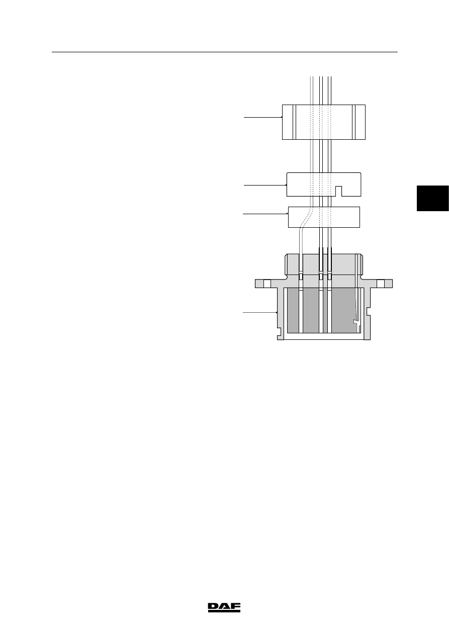
Removing 39-pin connector contacts

1. Loosen union G.

2. Push pressure ring H and seal K back

slightly over the wiring.

3. Then eject the contacts from connector

housing F using a special ejector tool from

contact kit A or B.

Fitting 39-pin connector contacts

1. Fit union G, pressure ring H over the wiring.

2. Fit new contacts to the wires using the

correct tool.

3. Insert the wires and contacts through

seal K.

4. Press the contacts to their definitive

positions in connector housing F.

5. Press seal K against connector housing F.

6. Position pressure ring H so that the two

ridges on the side of connector housing F

fall into the pressure ring recesses.

7. Tighten union G by hand.

Note:

-

Pressure ring H has contact numbers (their

purpose is to enable the contacts to be

positioned correctly). These contact

numbers must be in the same position as

the contact numbers on the connector

housing.

-

When an incorrectly positioned wire is

removed the seal will leak. If a new wire is

not inserted a sealing plug should be fitted.

E500477

G

H

K

F

3

 200440

5

WIRING REPAIR

Removal and installation

LF45/55 series

2-8

Removing contacts from 39-pin connector

counterpart

1. Loosen end union nut A and tapered

coupling nut B and push these as far as

possible back over the insulation pipe.

2. Push pressure ring H and seal K as far as

possible back over the wiring harness.

3. Push union E back over the wiring harness.

4. Carefully remove the sealing ring (2).

5. Carefully loosen the locking lugs (3) in

connector housing F.

6. Remove centring sleeve D from connector

housing C.

7. Then eject the contacts from connector

housing C using a special ejector tool from

contact kit A or B.

Fitting contacts in 39-pin connector

counterpart

1. Push end union nut A and tapered coupling

nut B as far as possible back over the

insulation pipe.

2. Fit the centring sleeve (D) in connector

housing C so that all openings are

positioned opposite one another.

3. Check that all locking lugs (3) are

positioned in the lock openings (1).

4. Insert the wires without contacts through

pressure ring H and seal K.

5. Fit new contacts to the wires using the

correct tool.

6. Feed the cable harness through tapered

coupling nut B.

7. Press seal K against connector housing C.

8. Position pressure ring H so that the two

ridges on the side of connector housing C

fall into the pressure ring recesses.

9. Press the connector pins into their correct

positions in connector housing C.

10. Fit sealing ring (2) around centring sleeve D

and press it until the stop of connector

housing C.

2

D

C

E

K

H

B

A

3

1

E500478

3

 200440

5

LF45/55 series

Removal and installation

WIRING REPAIR

2-9

Note:

-

When carrying out the last two steps it is

important not to twist the cable harness as

this can lead to serious damage (wire

breakage).

-

Tighten the respective union nuts by hand.

Do not use tools (pliers) to do this.

11. Screw tapered coupling nut B onto

connector housing C.

12. Screw end union nut A (with insulation pipe)

onto tapered coupling nut B.

2.3 FITTING CONTACTS TO ELECTRICAL WIRES

The increasing application of electronics in

vehicles means a much broader range of

connectors, contacts and wiring is being used.

The result of this is that more attention has to be

paid to making and repairing connections.

The following criteria should be taken into

account:

1. Wires with a reduced insulation thickness,

with retention of the mechanical properties,

for use with core sections from 0.5 to

2.5 mm

2

.

2. Wires with a normal insulation thickness, for

use with core sections from 4 to 120 mm

2

.

3. Wires for various temperature ranges:

T1: from --40_C to +70_C (in cab and

chassis) and

T2: from --40_C to +100_C (in engine

compartment and gearbox)

Note:

In view of the mechanical strength required, the

minimum permissible core section is 1 mm

2

,

with the exception of cab wiring. At certain

points this may be 0.5 mm

2

.

To ensure the reliability of systems and

connections, the following points should be

observed when repairs or extensions are made

to the wiring:

3

 200440

5

WIRING REPAIR

Removal and installation

LF45/55 series

2-10

A. Always choose the following:

-

the correct type of contact

-

the correct wire diameter for the

contact used

-

the correct type of contact material

(tin-plated, silver-plated or gold-plated)

B. Use the right tool for the job. Wire ends are

always clamped to a contact. Special

crimping tools have been developed for this

purpose.

Note:

Connections will only be reliable if these

crimping tools are used and the contact is fitted

in the correct hole.

C. Strip the correct length of wire. Always use

stripping pliers.

The rule of thumb is:

strip length = crimp-sleeve length + 1 mm.

Make sure that the core is not damaged

during stripping or problems may occur after

some time.

Note:

A good connection will only be obtained if points

A, B and C are complied with. This implies that

both the copper core and the insulation are

firmly clamped in place.

Crimping wire to a contact

Choose the right crimping tool and place the

contact in the correct hole.

Note:

The proper crimping tool for each contact can be

found through “Parts Rapido”.

The contact may never be in a twisted, slanting

or slid position (X) in the press clamp opening.

E501500

3

 200440


Content   ..  342  343  344  345   ..