DAF LF45, LF55 Series. Manual - part 338


  Index      DAF     DAF LF45, LF55 Series - service repair manual


Search            


Content   ..  336  337  338  339   ..


DAF LF45, LF55 Series. Manual - part 338


5

LF45/55 series

General

COMPONENTS

1-1

1. GENERAL

1.1 MULTIMETER

The Fluke 87 multimeter allows you to select

various measuring options:

Units of measurement

The multimeter should be set to the range for

the unit of measurement required.

For example, the voltage, current or resistance

range.

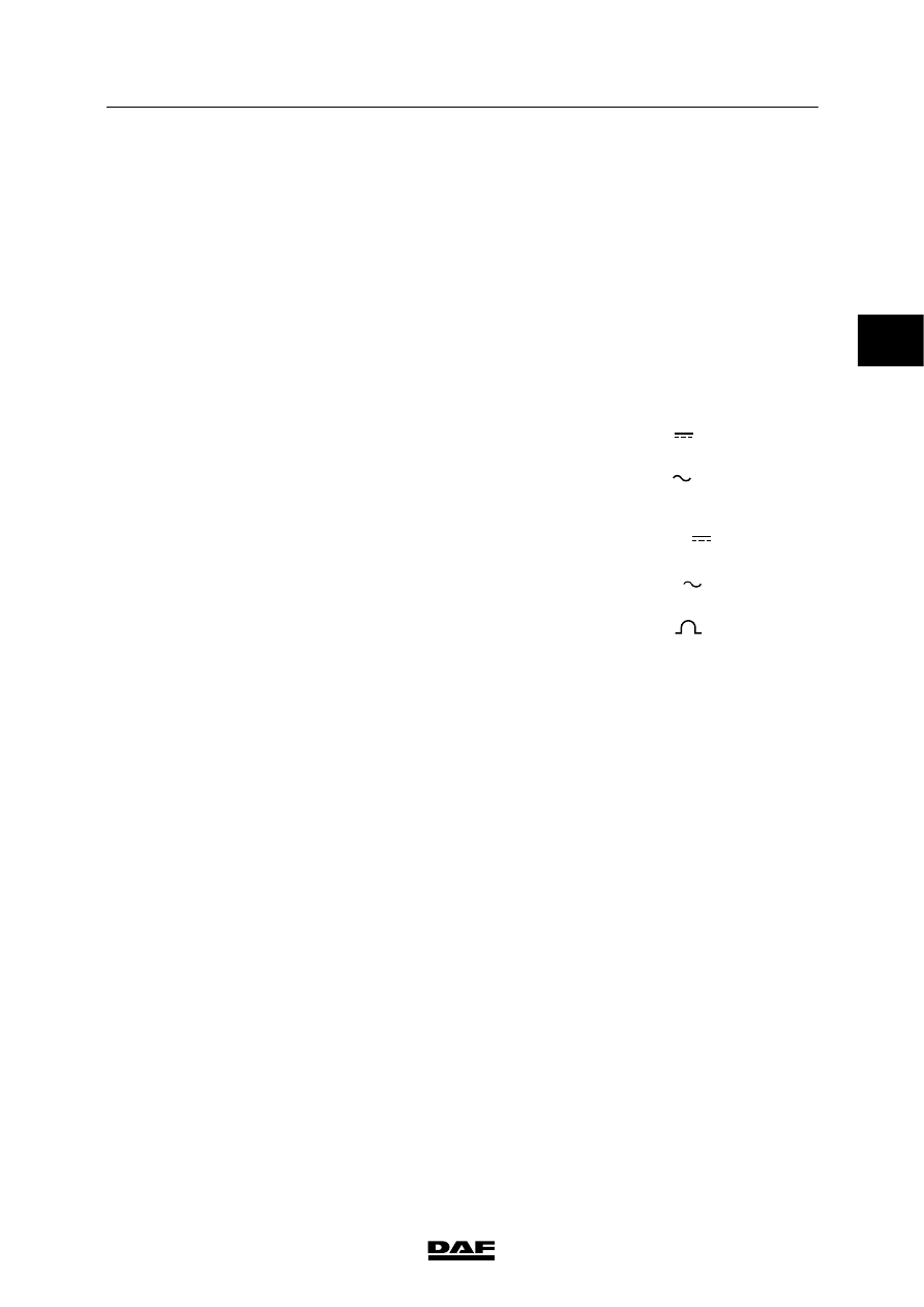
The units of measurement are indicated by

symbols on the meter. The following symbols

are used.

1.

DC voltage

2.

AC voltage

3.

DC current

4.

AC current

5.

resistance

6.

duty cycle

7.

frequency

DCV - V 

ACV - V

DCA - A   

ACA -A

Ohm - 

%

Hz 

1

2

3

4

5

6

7

W 5 01 004

2

 200440

5

COMPONENTS

General

LF45/55 series

1-2

1.2 SCOPEMETER

Diagnostics in modern electronic systems is

steadily becoming more complex.

Using a multimeter on its own is not always

sufficient to diagnose a fault.

The scopemeter allows complex signals to be

measured.

Practical examples of complex signals are:

-

PWM signals

-

deformation of signals

-

CAN-bus signals

1.3 SIGNAL MEASUREMENTS

Sine-wave signal (AC voltage)

This signal regularly changes polarity with

respect to the “0” line

+

-

0

Frequency

The frequency is shown in Hertz (Hz).

The number of complete sines per second is the

frequency of the signal (3 Hz in the diagram).

t = 1 second

+

-

t

1

2

3

0

Voltage

If the number of sines per second increases, not

just the frequency increases but also the

voltage. This depends on the type of sensor.

+

-

W 5 01 002

0

2

 200440

5

LF45/55 series

General

COMPONENTS

1-3

Measuring a sine-wave signal

The sine-wave signal can be measured in the

following ways using a multimeter:

-

with the multimeter in the frequency

(Hz) position.

In this way, the number of complete sines

per second is measured.

-

multimeter in the AC voltage position.

In this way, the average value of the

supplied voltage is measured.

Sine-wave signals in the vehicle

-

Wheel speed sensor output signal

-

Engine speed sensor output signal.

Square-wave signal

Square-wave signals are signals with only two

voltage levels, both of which have the same

duration in principle (t1 is equal to t2).

+

0

t

2

t

1

If the duration is different for the two levels (t1 is

not equal to t2), the signal is also called “pulse

train”.

t

1

t

2

0

+

Duty cycle

The duty cycle is the ratio between the two

voltage levels, expressed as a percentage.

A

x 100%

B

x 100%

The voltage level ratio of a pulse train may

change (for example, when the vehicle speed

increases).

A

B

0

+

Voltage

If the duty cycle increases, the average voltage

will also increase.

0

+

A

B

W 5 01 001   

2

 200440

5

COMPONENTS

General

LF45/55 series

1-4

Measuring a square-wave signal

The square-wave signal can be measured in the

following ways using a multimeter:

-

with the multimeter in the duty cycle

(%) position.

In this way, the voltage level ratio is

measured.

-

multimeter in the DC voltage position.

In this way, the average value of the

supplied voltage is measured.

Square-wave signals in the vehicle

-

Output signal of the vehicle speed sensor

-

Vehicle speed signal from tachograph to

electronic units

2

 200440


Content   ..  336  337  338  339   ..