DAF LF45, LF55 Series. Manual - part 314


  Index      DAF     DAF LF45, LF55 Series - service repair manual


Search            


Content   ..  312  313  314  315   ..


DAF LF45, LF55 Series. Manual - part 314


©

 200416

3-5

Description of components

CE ENGINE FUEL SYSTEM

ΛΦ45/55 series

4

5

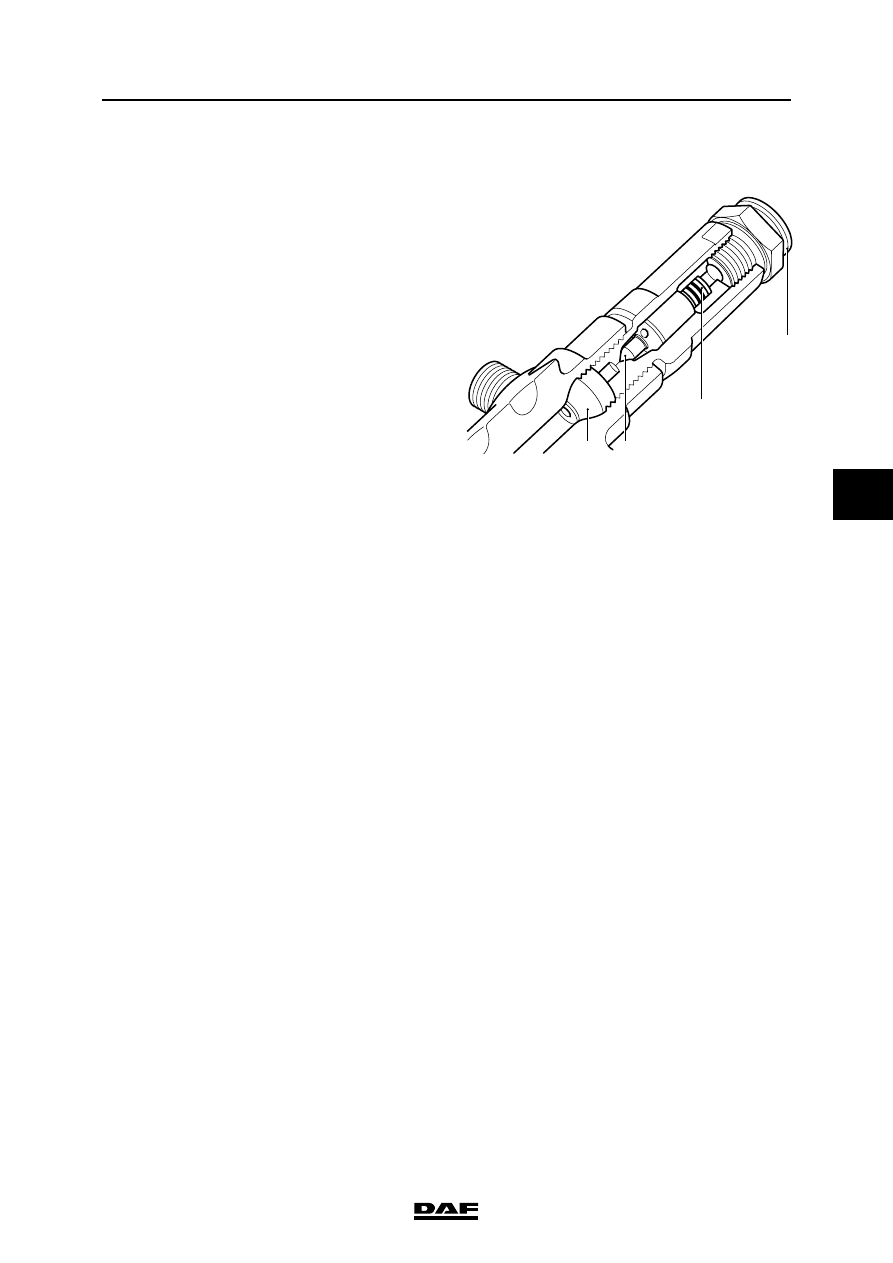
3.4 FUEL RAIL PRESSURE-LIMITING VALVE

The fuel rail has a pressure-limiting valve so that 

the rail pressure is maintained at a safe value in 

emergency situations.

The fuel rail pressure control circuit is normally 

active. This consists of the fuel lift pump, fuel 

pump control solenoid valve, high-pressure 

pump, fuel rail, rail pressure sensor and 

electronic unit. If a fault occurs, the rail pressure 

can no longer be controlled. This can rise to the 

actuating pressure of the fuel rail pressure-

limiting valve. This pressure is approx. 1650 bar. 

In the open position all surplus fuel flows without 

pressure to the fuel tank return connection.

The valve includes a sealing cone (1), a valve 

body (2), a spring (3) and a return connection with 

quick-release coupling (4).

i400592

1

2

3

4

CE ENGINE FUEL SYSTEM

3-6

©

 200416

Description of components

5

ΛΦ45/55 series

4

3.5 FUEL RETURN OVERFLOW VALVE

The injectors are mounted in the cylinder head. 

The injectors do not have a separate return 

connection. In place of this there is a longitudinal 

bore in the cylinder head that meets the injector 

bores of all cylinders coinciding with the height of 

the return ports of the injectors. A pressure relief 

valve is mounted at the end of the bore to prevent 

vapour bubbles forming in it and to prevent it 

emptying after the engine is turned off. This valve 

maintains a residual pressure in relation to the 

return pressure of 1.2 to 2.0 bar.

The pressure relief valve consists of a spring-

loaded plunger (1) and a housing (2) with quick-

release inlet and outlet connections (A and B 

respectively).

A

B

1

2

i400861

©

 200416

4-1

Inspection and adjustment

CE ENGINE FUEL SYSTEM

ΛΦ45/55 series

4

5

4. INSPECTION AND ADJUSTMENT

4.1 BLEEDING THE FUEL SYSTEM

Stop pumping as soon as a greater 

resistance is felt. If you continue 

pumping, the fuel system may 

become internally damaged.

Note:

When the hand pump is used, the fuel system will 

be automatically bled. Air will be fed back to the 

tank through the return pipe.

1.

Unscrew the button of the primer pump and 

pull it out.

2.

Use the primer pump until a clearly higher 

resistance is perceptible.

3.

Press the button and tighten it.

}

G0 00 209

CE ENGINE FUEL SYSTEM

4-2

©

 200416

Inspection and adjustment

5

ΛΦ45/55 series

4

4.2 CHECKING FUEL LIFT PUMP PRESSURES

When inspecting the fuel pressure, 

fuel will escape. Collect the fuel and 

avoid the risk of fire. 

Dirt in the fuel system can lead to 

significant damage to parts of the 

system. Prevent this by cleaning the 

parts before disassembly and then 

sealing all open connections.

Checking underpressure on suction side of 
fuel lift pump
1.

Disconnect the fuel pipe from the electronic 

unit cooling plate to the fuel lift pump on the 

suction side of the fuel lift pump; see 

"Removal and installation".

2.

Fit the adapter (1), special tool 

(DAF no. 1329476), between the pipe which 

has been removed and the fuel lift pump and 

couple a pressure gauge (2) to this adapter.

3.

Bleed the fuel system.

4.

Measure the underpressure when the engine 

is idling. Compare the readings with the 

specified values. See "Technical data".

5.

Remove the pressure gauge and the adapter 

and fit the fuel pipe.

6.

Bleed the fuel system, start the engine and 

check the fuel system visually for leaks if no 

further measurements are to be carried out.

Checking fuel pressure in fuel lift pump in 
front of fuel fine filter
1.

Disconnect the fuel pipe from the lift pump to 

the fuel fine filter on the delivery side of the 

lift pump; see "Removal and installation".

2.

Fit the adapter (1), special tool 

(DAF no. 1329476), between the pipe which 

has been removed and the fuel lift pump and 

couple a pressure gauge (2) to this adapter.

3.

Bleed the fuel system.

4.

Start the engine and measure the pressure 

when the engine is idling. Compare the 

readings with the specified values. See 

"Technical data".

5.

Remove the pressure gauge and the adapter 

and fit the fuel pipe.

}

}

i400883

2

1

i400883

2

1


Content   ..  312  313  314  315   ..