DAF LF45, LF55 Series. Manual - part 311
©
200416
2-5
General
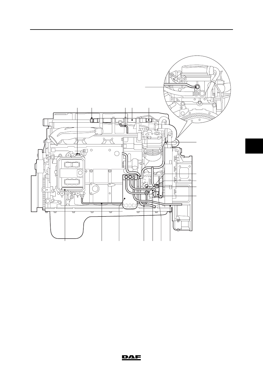
CE ENGINE FUEL SYSTEM
ΛΦ45/55 series
4
5
Location of components, production date
2003-49 (chassis number 0L253643)
1
2
3 4
5
6
7
11
13
17
18
16
10
9
8
i400872
14
15
12
|
|
|
© 200416 2-5 General CE ENGINE FUEL SYSTEM ΛΦ45/55 series 4 5 Location of components, production date 2003-49 (chassis number 0L253643) 1 2 3 4 5 6 7 11 13 17 18 16 10 9 8 i400872 14 15 12 |