DAF LF45, LF55 Series. Manual - part 298


  Index      DAF     DAF LF45, LF55 Series - service repair manual


Search            


Content   ..  296  297  298  299   ..


DAF LF45, LF55 Series. Manual - part 298


©

 200416

5-21

Removal and installation

BE ENGINE FUEL SYSTEM

ΛΦ45/55 series

4

2

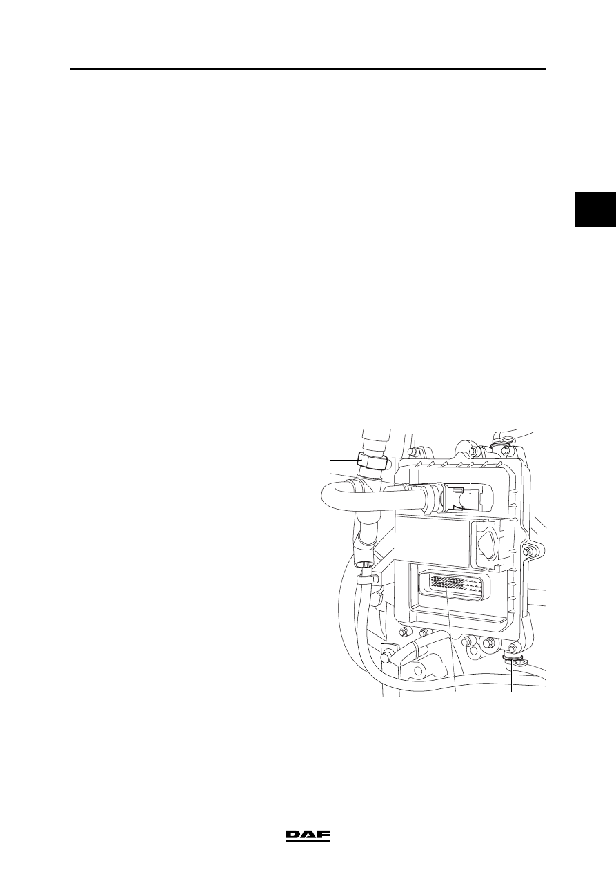
5.11 REMOVAL AND INSTALLATION, ELECTRONIC UNIT COOLING PLATE

When removing the cooling plate, 

fuel will escape. Collect the fuel and 

avoid the risk of fire. 

Dirt in the fuel system can lead to 

significant damage to parts of the 

system. Prevent this by cleaning the 

parts before disassembly and then 

sealing all open connections.

Note:

The electronic unit, together with the cooling 

plate, must first be removed from the engine 

block, after which the cooling plate must be 

demounted.

Removing electronic unit cooling plate
1.

Disconnect the earth lead from the battery 

terminal.

2.

To prevent dirt from entering, first clean the 

area around the fuel connections.

3.

Remove the fuel pipes (1) on the cooling 

plate of the electronic unit.

4.

Uncouple the electrical connectors (2) from 

the electronic unit and loosen the attachment 

clip (3) from the cable harness.

5.

Remove the attachment bolts by which the 

electronic unit is fitted to the engine block.

6.

Remove the electronic unit and cooling plate.

7.

Remove the attachment bolts by which the 

electronic unit is fitted to the cooling plate 

and remove the cooling plate.

}

}

i400500

3

2

1

1

2

2

BE ENGINE FUEL SYSTEM

5-22

©

 200416

Removal and installation

2

ΛΦ45/55 series

4

Installing electronic unit cooling plate
1.

Clean the cooling side of the electronic unit 

and the cooling plate.

2.

Inspect the sealing surfaces of the cooling 

plate and the electronic unit for damage and 

smoothness.

3.

Fit a new sealing rubber (1) in the cooling 

plate.

4.

Fit the cooling plate to the electronic unit and 

fit the bolts attaching the two parts. Tighten 

the attachment bolts to the specified torque. 

See "Technical data".

5.

Fit the electronic unit and cooling plate to the 

engine block and fit the attachment bolts. 

Tighten the attachment bolts to the specified 

torque. See "Technical data". 

6.

Connect the electrical connectors to the 

electronic unit and attach the cable harness 

with the clips.

7.

Connect the quick-release couplings of the 

fuel pipes to the electronic unit cooling plate.

8.

Bleed the fuel system. See "Inspection and 

adjustment".

9.

Fit the earth lead to the battery terminal.

10. Start the engine and check the fuel system 

for leaks.

i400819

1

©

 200416

5-23

Removal and installation

BE ENGINE FUEL SYSTEM

ΛΦ45/55 series

4

2

5.12 REMOVAL AND INSTALLATION, FUEL RETURN OVERFLOW VALVE

When removing the fuel return 

overflow valve valve, fuel will 

escape. Collect the fuel and avoid 

the risk of fire.

Dirt in the fuel system can lead to 

significant damage to parts of the 

system. Prevent this by cleaning the 

parts before disassembly and then 

sealing all open connections.

Removing the fuel return overflow valve
1.

To prevent dirt from entering, first clean the 

area around the fuel return connection.

2.

Remove the fuel return pipe (1) on the fuel 

return overflow valve (2) and plug the pipe.

3.

Remove the fuel return overflow valve and 

collect the escaping fuel.

Installing the fuel return overflow valve
1.

Install the fuel return overflow valve. Haal het 

brandstofretour-overstroomventiel aan met 

het voorgeschreven aanhaalmoment, zie 

hoofdgroep "Technische gegevens".

2.

Connect the quick-release couplings of the 

fuel return pipe to the fuel return overflow 

valve.

3.

Start the engine and check the fuel system 

for leaks.

}

}

1

2

i400502

BE ENGINE FUEL SYSTEM

5-24

©

 200416

Removal and installation

2

ΛΦ45/55 series

4

5.13 REMOVAL AND INSTALLATION, LOW-PRESSURE FUEL PIPES

When removing the low-pressure 

fuel pipes, fuel will escape. Collect 

the fuel and avoid the risk of fire. 

Dirt in the fuel system can lead to 

significant damage to parts of the 

system. All open connections must 

therefore be sealed.

The low-pressure fuel pipes may have two 

different types of quick-release coupling.

VOSS quick-release coupling

}

}

i400881


Content   ..  296  297  298  299   ..