DAF LF45, LF55 Series. Manual - part 276


  Index      DAF     DAF LF45, LF55 Series - service repair manual


Search            


Content   ..  274  275  276  277   ..


DAF LF45, LF55 Series. Manual - part 276


©

 200508

4-7

Demounting and mounting

PROP SHAFTS

ΛΦ45/55 series

3

10

5.

Push the spider down again in the direction 

of the shaft fork. Again, continue until the 

spider touches the fork.

6.

The spider and the drive flange can now be 

tipped out of the shaft fork.
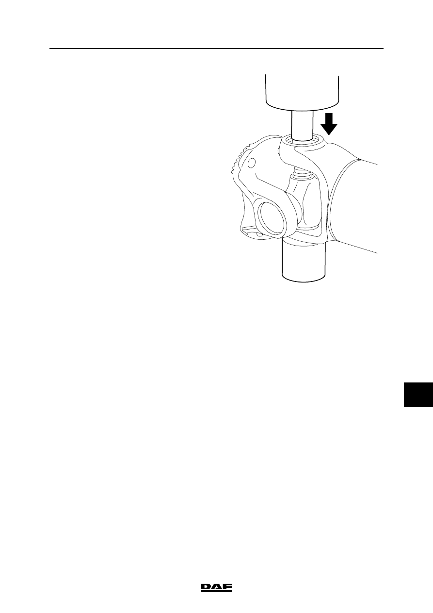
7.

Place the drive flange on a bush underneath 

a press and press the entire spider including 

bearings and drive flange down, until the 

spider touches the fork of the drive flange.

8.

Rotate the drive flange 180

″ and remove the 

bearing that has just been pressed out. 

Place the drive flange back on the bush.

9.

Push the spider down again in the direction 

of the shaft fork. Again, continue until the 

spider touches the fork.

10. The spider can now be tipped out of the drive 

flange fork.

Note:

When spiders are being replaced, always 

replace them including their bearings.

11. Check the components to be reused for any 

cracks and/or damage.

Assembly, universal joint

Note:

After assembly, it must be possible to move 

the drive flanges and spiders by hand. When 

mounting the spider, Seeger rings of the 

same thickness must be used.

1.

Install the sealing rings in their proper 

positions on the bearings and lubricate them 

lightly so that the needles remain in place.

2.

Press one bearing partly into the drive 

flange.

W306011-2

PROP SHAFTS

4-8

©

 200508

Demounting and mounting

10

ΛΦ45/55 series

3

3.

Tip the spider into the drive flange.

Note:

Maintenance-free spiders do not have an 

assembly direction. In the case of spiders 

fitted with lubricating nipples, hole A for the 

lubricating nipple must point towards the 

shaft.

4.

Slide the spider a little into the installed 

bearing and place everything on a bush 

underneath a press. The opposite bearing 

can now be pressed into the fork, the spider 

serving as a guide. During the pressing 

action, the spider must be able to move 

freely.

A

W306014-2

W306017-2

©

 200508

4-9

Demounting and mounting

PROP SHAFTS

ΛΦ45/55 series

3

10

5.

Continue to press the bearing until a Seeger 

ring can be installed on the side being 

pressed. Install the Seeger ring and press 

the opposite bearing further into the fork. 

Again, the Seeger ring can now be installed.

6.

Install the sealing rings in their proper 

positions on the prop shaft bearings and 

lubricate them lightly so that the needles 

remain in place.

7.

Press one bearing partly into the prop shaft.

8.

Slide the spider a little into the installed 

bearing and place everything on a bush 

underneath a press. The opposite bearing 

can now be pressed into the fork, the spider 

serving as a guide. During the pressing 

action, the spider must be able to move 

freely.

9.

Continue to press the bearing until a Seeger 

ring can be installed on the side being 

pressed. Install the Seeger ring and press 

the opposite bearing further into the fork. 

Again, the Seeger ring can now be installed. 

10. If fitted, install the lubricating nipple and 

lubricate the spider.

11. Install the prop shaft and/or intermediate 

shaft.

W306013-2

W306015-2

PROP SHAFTS

4-10

©

 200508

Demounting and mounting

10

ΛΦ45/55 series

3


Content   ..  274  275  276  277   ..