DAF LF45, LF55 Series. Manual - part 274
©
200508
3-1
Removal and installation
PROP SHAFTS
ΛΦ45/55 series
3
10
3. REMOVAL AND INSTALLATION
3.1 REMOVING AND INSTALLING SPICER PROP SHAFT/INTERMEDIATE SHAFT
ASSEMBLY
Removing prop shaft/intermediate shaft
assembly
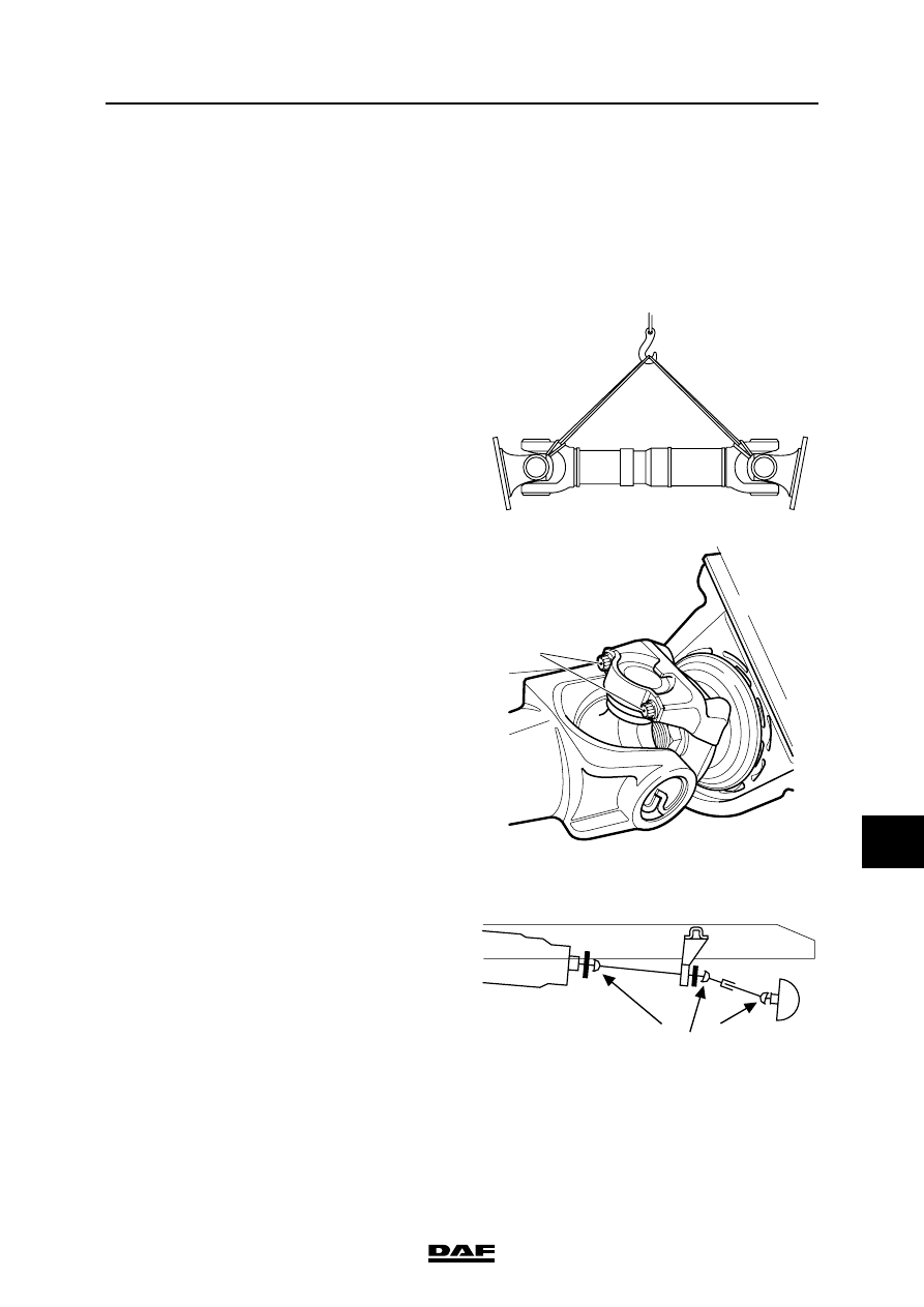
Note:
When removing one of the shafts in vehicles with
multiple shafts (prop shaft and intermediate
shafts), the other shaft must be tied to the chassis
or intermediate beam in such a way that it does
not obstruct the various operations. Always
transport and store shafts horizontally to avoid
damage and subsequent imbalance. Support the
shaft in at least two places. If possible, hang the
shaft in a hoist, using two sturdy ropes.
1.
Remove the attachment bolts from the
flanges and/or clamping pieces (1), and
carefully lower the shaft to the ground.
2.
Now remove the shaft from under the
vehicle.
Installing prop shaft/intermediate shaft
assembly
Note:
After repairs have been carried out or a shaft has
been replaced, the forks of all shafts must be
aligned.
1.
Fit the shaft under the vehicle. Use a hoist if
possible.
2.
Fit the attachment bolts. Tighten the
attachment bolts to the specified torque. See
"Technical data".
W 3 06 016
V3 00 377
1
=
=
W 3 06 019