DAF LF45, LF55 Series. Manual - part 245


  Index      DAF     DAF LF45, LF55 Series - service repair manual


Search            


Content   ..  243  244  245  246   ..


DAF LF45, LF55 Series. Manual - part 245


©

 200508

1-1

General

ZF 6S-850 GEARBOX

ΛΦ45/55 series

3

5

1. GENERAL

1.1 GENERAL

Gearbox type
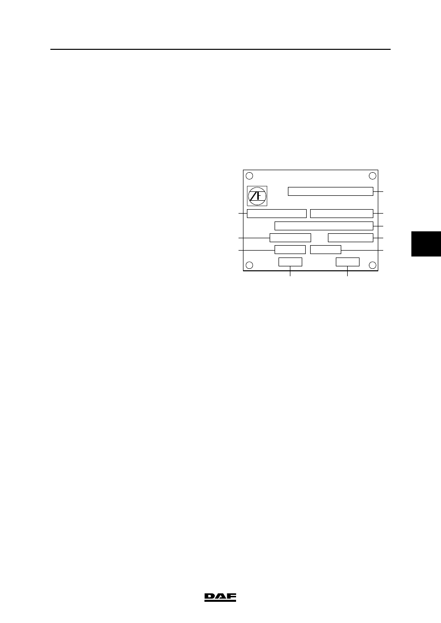
Each gearbox has a type plate attached to it, 

indicating the type of gearbox. You can also find 

this data on the identity card for the vehicle 

concerned.

ZF gearbox type plate

V300049

1

2
4
5

3

8

6

7

10

9

1.

Type of gearbox

2.

Serial no. (ZF)

3.

Parts list (ZF)

4.

Specification no.

5.

Pulse generator ratio

6.

Gearbox ratio

7.

Engine speed using PTO

8.

PTO speed

9.

Gearbox oil capacity

10.

Oil specification

ZF 6S-850 GEARBOX

1-2

©

 200508

General

5

ΛΦ45/55 series

3

1.2 SYSTEM DESCRIPTION, ZF 6S-850 GEARBOX

The gearbox consists of six synchromesh forward 

gears and one non-synchromesh reverse gear.

The first and second gears have double-cone 

synchronisation.

The sixth gear is a direct drive or an overdrive, 

depending upon the model.

V300466

©

 200508

2-1

Description of components

ZF 6S-850 GEARBOX

ΛΦ45/55 series

3

5

2. DESCRIPTION OF COMPONENTS

2.1 SYNCHRONISER

B-lock synchronisation

The synchroniser consists of the following parts:

1

8

2

2

7

4

7

1

6

2 3

3 2

5

1.

gear wheel

2.

selector ring

3.

synchromesh ring 

4.

selector sleeve

5.

pressure spring

6.

thrust piece

7.

selector sleeve

8.

main shaft

ZF 6S-850 GEARBOX

2-2

©

 200508

Description of components

5

ΛΦ45/55 series

3

In neutral, the selector sleeve (7) is in the centre 

position.

Pressure springs (5) push the thrust pieces (6) 

into a wedge-shaped recess in the selector 

sleeve (7).

The gear wheels (1) and corresponding selector 

rings (2) move freely around the main shaft (8).

If the selector sleeve (7) is shifted to the right from 

the neutral position, the synchromesh ring (3) is 

pushed against the friction cone of the selector 

ring (2) by the thrust pieces (6).

The difference in speed immediately turns the 

synchromesh ring (3) as far as a stop on the 

selector sleeve support (4), which is not in the 

figure, and thus prevents further movement of 

selector sleeve (7).

As a result of continued pressure on selector 

sleeve (7) (friction), the speed of the gear (1) to 

be shifted with selector ring (2) matches the 

speed of the main shaft (8).

The bevelled sides of the teeth on the 

synchromesh ring (3) and selector sleeve (7) 

cause synchromesh ring (3) to be turned back 

slightly after synchronisation.

This releases the lock and allows selector sleeve 

(7) to be moved into the teeth of selector ring (2).

As a result, the relevant gear is engaged.

W 3 03 046

2
3
5
1
4

7

6

8

1

8

2

2

7

4

7

1

6

2 3

3 2

5


Content   ..  243  244  245  246   ..