DAF LF45, LF55 Series. Manual - part 200


  Index      DAF     DAF LF45, LF55 Series - service repair manual


Search            


Content   ..  198  199  200  201   ..


DAF LF45, LF55 Series. Manual - part 200


©

 200505

4-31

Removing and installing

CE ENGINE

ΛΦ45/55 series

2

5

4.22 REMOVAL AND INSTALLATION, TIMING GEAR CASE

Removing the timing gear case
1.

Remove the flywheel housing.

2.

Remove the steering pump.

3.

Remove the air compressor.

4.

Remove the high-pressure pump.
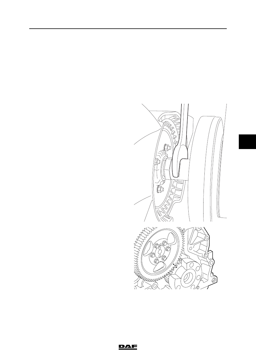
5.

Use an open-end spanner on the fan shaft to 

crank the crankshaft until the marks in the 

crankshaft gear and camshaft gear match. 

The crankshaft gear has a punched hole in 

the tooth which has to fall into the tooth depth 

of the camshaft gear marked with a punched 

hole.

6.

Remove the camshaft gear.

7.

Loosen the sump bolts and remove the sump 

bolts fitted in the timing gear case.

M201318

M201146

CE ENGINE

4-32

©

 200505

Removing and installing

5

ΛΦ45/55 series

2

8.

Remove the attachment bolts from the timing 

gear case and remove it.

Installing the timing gear case
1.

Apply a sealant to the sealing surface of the 

cylinder block. See "Technical data". Apply 

the sealant in accordance with the pattern 

and at the indicated location. The bead has 

to be 1.5 to 2.0 mm thick. Fit the timing gear 

case with liquid sealant and tighten the 

attachment bolts to the specified torque. See 

"Technical data".

Note:

If too much sealant is used, or if the sealant 

is applied in a wrong place, this may cause 

obstruction of an oil channel or oil sump 

ventilating duct. This could result in serious 

damage.

2.

Fit the sump bolts and tighten them to the 

specified torque. See "Technical data".

3.

Fit the camshaft gear.

4.

Fit the high-pressure pump.

5.

Fit the air compressor.

6.

Fit the steering pump.

7.

Fit the flywheel housing.

M201147

M201242

©

 200505

4-33

Removing and installing

CE ENGINE

ΛΦ45/55 series

2

5

4.23 REMOVAL AND INSTALLATION, FRONT CRANKSHAFT SEAL

Removing the front crankshaft seal
1.

Remove the attachment bolts of the fan and 

place the fan in the wind tunnel.

2.

Remove the poly-V-belt.

3.

Remove the attachment bolts from the 

vibration damper and remove the damper 

along with the crankshaft pulley.

4.

Fit the threaded spindle (2) of the special tool 

(DAF no. 1453179) on the crankshaft flange.

5.

Screw the push/pull piece (1) onto the 

spindle up to the engine panel.

Note:

Mark the drill at a length of 18 mm using a 

piece of tape.

6.

Drill a hole through the base plate to the tape 

marking and fit a screw in the seal to keep 

the base plate in its place.

7.

Drill the other five holes and fit screws.

8.

Turn the threaded spindle (2) clockwise until 

the seal has been removed.

M201069

2

1

CE ENGINE

4-34

©

 200505

Removing and installing

5

ΛΦ45/55 series

2

Installing the front crankshaft seal
1.

Clean and inspect the seal chamber. Even 

minimal damage may cause a leak.

2.

Fit the threaded spindle (2) of the special tool 

(DAF no. 1453179) on the crankshaft flange.

3.

Put a new seal over the crankshaft.

4.

Screw the push/pull piece (1) onto the 

threaded spindle (2) up to the seal.

5.

Turn the threaded spindle (2) anti-clockwise 

until the push/pull piece (1) is level with the 

top panel. The seal has been properly fitted 

once it is level with the engine panel.

6.

Remove the special tool.

7.

Inspect the vibration damper.

8.

Fit the crankshaft pulley and the vibration 

damper and tighten the attachment bolts to 

the specified torque. See "Technical data".

9.

Fit the poly-V-belt.

10. Fit the fan.

M201069

2

1


Content   ..  198  199  200  201   ..