DAF LF45, LF55 Series. Manual - part 189
©
200505
2-3
General
CE ENGINE
ΛΦ45/55 series
2
5
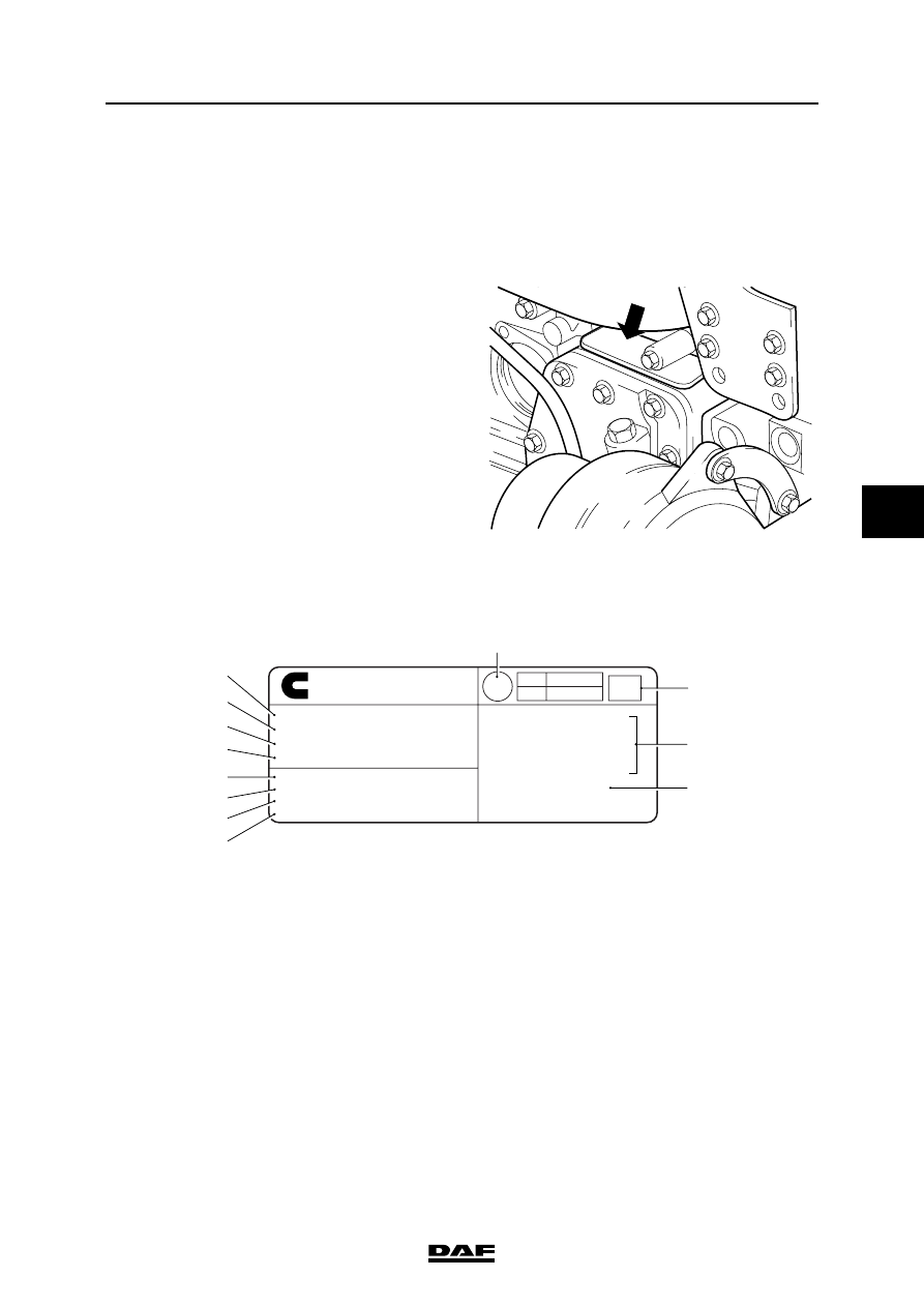
2.2 IDENTIFICATION
Engine number
The engine number is stamped front right in the
cylinder block, at the top of the lubricating oil
cooler housing.
Engine identification plate
The engine identification plate is located at the
top of the flywheel housing or on the valve cover,
depending on the production date.
1.
Cubic capacity
2.
Engine output
3.
Valve clearance
4.
Idle engine speed
5.
Engine number
6.
Production date
7.
Client specification
8.
DAF type designation
9.
Indication of country of origin
10. Free acceleration smoke level (K factor)
11. Type approval numbers
12. Cummins type designation
XXXXXXX
M2 01 138
MADE IN GREAT BRITAIN BY
CUMMINS ENGINE CO LTD
www.cummins.com
Displacement........................................ 5.9 Litres
Gross Power.........................136kW @ 2500 rpm
Valve lash - (cold)
Int .254 mm, Exh .508 mm
Low idle speed.............................. 600 - 800 rpm
Engine Serial No ................................. 21410538
Date of mfg ........................................... 26/06/00
Customer Spec ......................................1396009
DAF ID ...................................................CE136C
E.C. Type Approal Numbers
e11*72/245*95/54*1413*00(ESA)
e11*88/77*1999/96A*1705*00
Model: - ISBe185 30
3286647
M201135
0.94
E11
24
031410
Cummins
¤
9
10
11
12
5
4
3
2
1
6
7
8