DAF LF45, LF55 Series. Manual - part 166


  Index      DAF     DAF LF45, LF55 Series - service repair manual


Search            


Content   ..  164  165  166  167   ..


DAF LF45, LF55 Series. Manual - part 166


©

 200505

3-11

Checking and adjusting

BE ENGINE

ΛΦ45/55 series

2

2

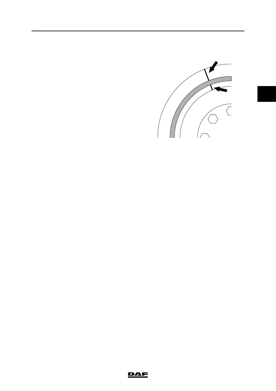
3.7 INSPECTION, VIBRATION DAMPER

1.

Check the reference lines. The reference 

lines should form a single line.

2.

Inspect the rubber part for damage or 

degradation. If the rubber part shows cracks 

or if there are bits of rubber missing, the 

vibration damper must be replaced.

3.8 INSPECTING THE CYLINDER HEAD

1.

Check the sealing plugs and expansion 

plugs of the cylinder head for leaks. If 

necessary, pressure-test the cylinder head.

2.

Inspect the cylinder head for damage to the 

sealing surface and any cracks.

3.

Check the cylinder head for smoothness 

using a straight edge and feeler gauge. See 

"Technical data".

Note:

The cylinder head must be replaced if it does 

not meet the specified values.

G0 00 199

BE ENGINE

3-12

©

 200505

Checking and adjusting

2

ΛΦ45/55 series

2

3.9 INSPECTING THE CYLINDER BLOCK

1.

Inspect the cylinder block for damage to the 

sealing surface and any cracks.

2.

Check the cylinder block for smoothness 

using a straight edge and feeler gauge. See 

"Technical data".

©

 200505

4-1

Removing and installing

BE ENGINE

ΛΦ45/55 series

2

2

4. REMOVING AND INSTALLING

4.1 REMOVAL AND INSTALLATION, ENGINE

Suspend the engine securely from 

the hoist, using approved lifting 

gear. 

Various fluids will be released when 

fluid pipes are removed. 

Collect these fluids. Personal safety 

and the risk of fire should always be 

considered.

Note:

Because of the large number of vehicle 

specifications, it is not feasible to exactly specify 

the engine removal and installation procedures 

for every vehicle.

This description only includes the most important 

points requiring attention.

-

Disconnect the earth lead from the battery 

terminal.

-

Avoid opening fluid systems as much as 

possible. If possible, remove and set aside 

the engine components.

-

When removing the engine, ensure that no 

parts or dirt fall into the engine, radiator or 

other components. All openings that are 

freed should therefore be plugged.

-

Wiring harnesses are vulnerable. If 

damaged, they may cause failures. Make 

sure these wiring harnesses are not live and 

are clear of moving parts.

-

Fit all attachment bolts and tighten them to 

the correct torque.

-

The engine should not be allowed to rest on 

the oil sump. Because the oil sump is made 

of sheet material, it will be severely damaged 

by the engine's weight.

-

The engine should not be allowed to rest on 

the flywheel housing. It can easily be 

damaged by the engine's weight.

}

BE ENGINE

4-2

©

 200505

Removing and installing

2

ΛΦ45/55 series

2

4.2 REMOVAL AND INSTALLATION, ENGINE MOUNTS

Suspend the engine securely from 

the hoist, using approved lifting 

gear. Various fluids will be released 

when fluid pipes are removed. 

Collect these fluids. Personal safety 

and the risk of fire should always be 

considered.

Removing the engine mounts
1.

Disconnect the earth lead from the battery 

terminal.

2.

Drain the coolant.

3.

Remove the hoses between the engine and 

the radiator.

4.

Remove the attachment bolts from the 

radiator torque rod bracket on the engine 

side.

5.

Remove the air inlet hoses between the 

engine and the air cooler. Plug the openings.

6.

Detach the air-conditioning pipes, if present, 

at the top of the radiator.

7.

Detach the heater hose bracket at the top of 

the radiator.

8.

Remove the oil supply pipe from the engine.

9.

Remove the lower connector from electronic 

unit ECS-DC3.

10. Remove the attachment bolts of the viscous 

fan clutch on the drive flange and place the 

viscous fan clutch with the fan in the wind 

tunnel.

11. Suspend the engine securely in the hoist.

12. Remove the engine mount attachment bolts 

at the front and rear of the engine.

13. Hoist the engine very carefully as far as 

necessary and support it properly.

14. Remove the engine mounts.

}


Content   ..  164  165  166  167   ..