DAF LF45, LF55 Series. Manual - part 155
©
200505
6-1
CE engine lubrication system
TECHNICAL DATA
ΛΦ45/55 series
2
0
6. CE ENGINE LUBRICATION SYSTEM
6.1 GENERAL
Oil pressure
Oil filter
Oil cooler
Lubricating oil pump
Lubricating oil pressure at engine idling speed
min. 0.69 bar
Lubricating oil pressure at full-load engine speed
min. 2.07 bar
Bypass pressure regulator opening pressure
3.52 bar
Type
disposable filter
Number
1
Location in the oil circuit
full flow
Oil cooler pressure test temperature
approx. 60
C
Oil section test pressure
4.5 - 5.0 bar
Opening pressure of bypass valve at a pressure
difference of
3.45 bar
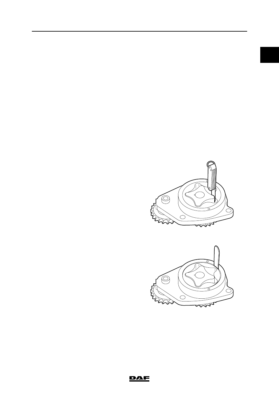
M201077
Maximum clearance,
inner rotor - outer
rotor
0.178 mm
M201076
Maximum clearance,
outer rotor - pump
housing
0.381 mm