DAF LF45, LF55 Series. Manual - part 153
©
200505
4-5
CE engine
TECHNICAL DATA
ΛΦ45/55 series
2
0
Flywheel/starter ring gear
Flywheel housing
Vibration damper
M201199
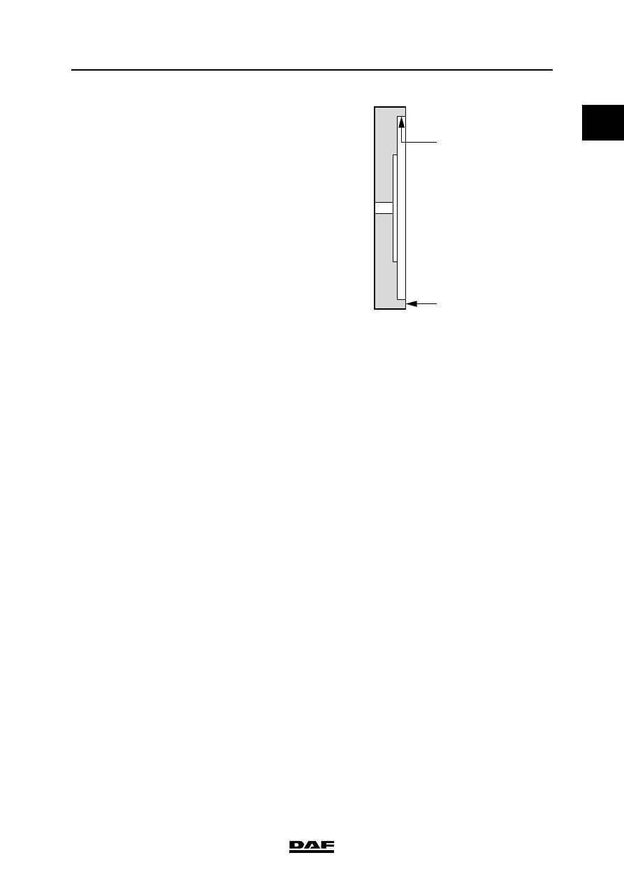
A
B
Radial run-out,
measured on the
inside of the flywheel
outer edge (A).
max. 0.127 mm
Axial deviation,
measured on the
flywheel outer edge
(B).
max. 0.406 mm
Heat starter ring gear
(max. 20 min.)
max. 125
C
Fit flywheel housing using sealant
Loctite 5205
Difference in thickness at 4 places must not
exceed:
6.35 mm