DAF 95XF. Manual - part 78


  Index      DAF     DAF 95XF Series - service repair manual


Search            


Content   ..  76  77  78  79   ..


DAF 95XF. Manual - part 78


2

Removal and installation

XE ENGINE

4-5

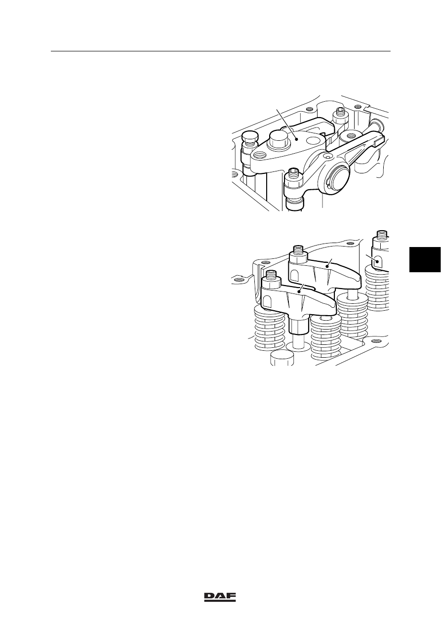
4.4 REMOVAL AND INSTALLATION, VALVE MECHANISM

Removing the valve mechanism
1.

Remove the valve covers.

2.

Remove the DEB or the lubricating-oil strip
(depending on model).

Note:
Place numbers on the rocker brackets (a)
and the bridges (2-3-4), to allow
reinstallation in the same position.

3.

Remove the rocker brackets (1).

4.

Remove the bridges (2-3-4).

Installing the valve mechanism

Note:
In engines equipped with a DEB, the
bridges (2-3-4) of the inlet and exhaust
valves are not the same.
In engines without a DEB, the bridges
(2-3-4) of the inlet and exhaust valves are
the same.

1.

Install the bridges (2-3-4) on the valves.

2.

Adjust the bridges (2-3-4), see chapter
“Checking and adjusting”.

3.

Tighten the rocker brackets (1) by hand.

Note:
Depending on the engine position, some
rocker brackets (1) will have to be
positioned against the pressure of the valve
springs.
The rocker bracket will resist this spring
pressure and can therefore not be
positioned correctly. By cranking the
crankshaft always

1

/

3

stroke using the

special tool (DAF no. 1310477), the rocker
brackets (1) can be tightened according to
the injection sequence 1-5-3-6-2-4.

M200559

1

M200560

3

2

4

5

ǹ 0008

2

XE ENGINE

Removal and installation

4-6

4.

Tighten the fixing bolts to the specified
torque. See main group “Technical data”.

5.

Install the DEB or the lubricating-oil strip
(depending on model). Install the
lubricating-oil strip in such a way that the
mark “cyl. 1/4” is located on cylinder 1 or
cylinder 4 respectively. For the tightening
torques of the fixing bolts, see main group
“Technical data”.

6.

Adjust the valve clearance and, if present,
the DEB clearance, see chapter
“Inspection and adjustment”.

7.

Fit the valve covers.

5

ǹ 0008

2

Removal and installation

XE ENGINE

4-7

4.5 REMOVAL AND INSTALLATION, CYLINDER HEAD

When the engine or parts thereof
are opened, dirt may enter. This
may result in serious damage to the
engine. You should therefore clean
the engine before opening it.

Removing the cylinder head
1.

Disconnect the earth lead from the battery
pole.

2.

Drain the coolant.

3.

Disconnect all electrical wiring around the
engine which is relevant for the removal of
the cylinder heads.

4.

Remove the inlet air hoses between the
engine and the intercooler.

5.

Remove the inlet pipe from the intercooler
to the turbocharger.

6.

Remove the compressor pipe from the air
inlet pipe to the compressor.

7.

Remove the reaction rod between the
engine and the radiator.

8.

Slacken the air-conditioning compressor
tensioning device, if present.

9.

Remove the fixing bolts of the
air-conditioning compressor attachment
bracket, if present.

10. Remove the heat shields from the exhaust

manifold.

11. Remove the fixing bolts from the exhaust

manifold and move the manifold and the
turbocharger a little away from the cylinder
heads.

12. Remove the hoses of the auxiliary heating,

if applicable.

5

ǹ 0008

2

XE ENGINE

Removal and installation

4-8

13. Remove the coolant filter, if present.

14. Remove the fuel leak-off pipe between the

fuel filter and the fuel leak-off pipe on the
inlet manifold.

15. Remove the entire fuel filter from the

coolant pipe.

16. Remove both sets of injection lines.

17. Remove the water hoses between the

thermostat housing and the radiator.

18. Remove the coolant pipe together with the

thermostat housing.

19. Remove the fixing bolts of the inlet manifold

and take it completely off the cylinder
heads.

20. Remove the valve covers.

21. Remove the injectors.

22. Remove the valve mechanism.

23. Remove the push rods.

24. Remove the valve sleeve.

25. Remove the cylinder head bolts.

26. Remove the cylinder head from the cylinder

block.

27. Remove any remaining gasket pieces from

the cylinder head and the cylinder block.

28. Check the cylinder block sealing faces.

5

ǹ 0008


Content   ..  76  77  78  79   ..