Chrysler Sebring, Stratus sedan, Sebring Convertible. Manual - part 480


  Index      Chrysler     Chrysler Sebring, Stratus sedan, Sebring Convertible - service repair manual 2001-2007 year


Search            


Content   ..  478  479  480  481   ..


Chrysler Sebring, Stratus sedan, Sebring Convertible. Manual - part 480


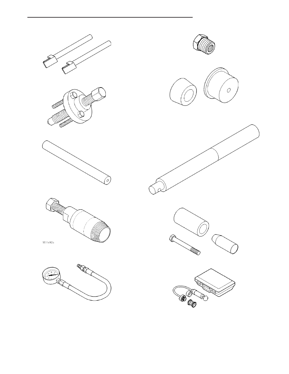
Connecting Rod Guides 8189

Crankshaft Sprocket Remover 6793

Crankshaft Sprocket Remover Insert C-4685-C2

Crankshaft Seal Remover 6771

Oil Pressure Gage C-3292

Adaptor 8406

Rear Crankshaft Seal Guide and Installer 6926-1 and

6926-2

Driver Handle C-4171

Front Crankshaft Oil Seal Installer 6780

Cooling System Tester 7700

JR

ENGINE 2.0L DOHC

9 - 23

ENGINE 2.0L DOHC (Continued)

Combustion Leak Tester C-3685-A

DRB III

T

with PEP Module OT-CH6010A

Pressure Transducer CH7059

Cylinder Compression Pressure Adaptor 8116

9 - 24

ENGINE 2.0L DOHC

JR

ENGINE 2.0L DOHC (Continued)

AIR CLEANER ELEMENT

REMOVAL

(1) Disconnect negative battery cable.
(2) Disconnect inlet air temperature sensor electri-

cal connector.

(3) Disconnect fresh air makeup hose from throttle

body air inlet hose.

(4) Disconnect PCV hose from intake manifold.
(5) Loosen hose clamp at throttle body air inlet

hose. Remove hose from throttle body.

(6) Push in on locking tabs to disengage air inlet

hose from air cleaner housing. Remove throttle body
air inlet hose and air cleaner element together.

(7) Separate air cleaner element from throttle body

air inlet hose (Fig. 7).

INSTALLATION

(1) Clean any debris from inside air cleaner hous-

ing.

(2) Install air cleaner element onto throttle body

air inlet hose.

(3) Install throttle body air inlet hose into air

cleaner housing. Push in on hose until an audible
“click” is heard from locking tabs.

(4) Install hose on throttle body. Tighten hose

clamp.

(5) Connect PCV hose to intake manifold.
(6) Connect fresh air makeup hose.
(7) Connect inlet air temperature sensor electrical

connector.

(8) Connect negative battery cable.

AIR CLEANER HOUSING

REMOVAL

(1) Disconnect negative battery cable.
(2) Disconnect inlet air temperature sensor electri-

cal connector.

(3) Disconnect fresh air makeup hose from throttle

body air inlet hose.

(4) Loosen hose clamp at throttle body air inlet

hose. Remove hose from throttle body (Fig. 8).

(5) Remove push pin securing air duct to upper

radiator support.

(6) Remove nut on bracket that holds air cleaner

housing.

(7) Pull air cleaner housing straight up off locating

pins (Fig. 8).

INSTALLATION

(1) Install air cleaner housing straight down on

locating pins (Fig. 8).

(2) Install nut on bracket that holds air cleaner

housing and tighten.

(3) Install push pin that secures air duct to upper

radiator support.

(4) Install throttle body air inlet hose to throttle

body. Tighten hose clamp.

(5) Connect fresh air makeup hose.
(6) Connect inlet air temperature sensor electrical

connector.

(7) Connect negative battery cable.

Fig. 7 Air Cleaner Housing 4cyl

Fig. 8 Air Cleaner Housing

JR

ENGINE 2.0L DOHC

9 - 25

CYLINDER HEAD

DESCRIPTION

The cross flow designed, aluminum cylinder head

contains dual over-head camshafts with four valves
per cylinder (Fig. 9). The valves are arrange in two
in-line banks. The intake valves face toward the
front of the vehicle. The exhaust valves face the dash
panel. The cylinder head incorporates powdered
metal valve guides and seats. The cylinder head is
sealed to the block using a multi-layer steel head
gasket and retaining bolts.

Integral oil galleries providing lubrication passages

to the hydraulic lash adjusters, camshafts, and valve
mechanisms.

DIAGNOSIS AND TESTING

CYLINDER HEAD GASKET

A cylinder head gasket leak can be located between

adjacent cylinders or between a cylinder and the
adjacent water jacket.

Possible indications of the cylinder head gasket

leaking between adjacent cylinders are:

• Loss of engine power

• Engine misfiring

• Poor fuel economy

Possible indications of the cylinder head gasket

leaking between a cylinder and an adjacent water
jacket are:

• Engine overheating

• Loss of coolant

• Excessive steam (white smoke) emitting from

exhaust

• Coolant foaming

CYLINDER-TO-CYLINDER LEAKAGE TEST

To determine if an engine cylinder head gasket is

leaking between adjacent cylinders, follow the proce-
dures in Cylinder Compression Pressure Test (Refer
to 9 - ENGINE - DIAGNOSIS AND TESTING). An
engine cylinder head gasket leaking between adja-
cent cylinders will result in approximately a 50–70%
reduction in compression pressure.

CYLINDER-TO-WATER JACKET LEAKAGE TEST

WARNING: USE EXTREME CAUTION WHEN THE
ENGINE IS OPERATING WITH COOLANT PRES-
SURE CAP REMOVED.

VISUAL TEST METHOD

With the engine cool, remove the coolant pressure

cap. Start the engine and allow it to warm up until
thermostat opens.

If a large combustion/compression pressure leak

exists, bubbles will be visible in the coolant.

COOLING SYSTEM TESTER METHOD

WARNING: WITH COOLING SYSTEM TESTER IN
PLACE, PRESSURE WILL BUILD UP FAST. EXCES-
SIVE

PRESSURE

BUILT

UP,

BY

CONTINUOUS

ENGINE OPERATION, MUST BE RELEASED TO A
SAFE PRESSURE POINT. NEVER PERMIT PRES-
SURE TO EXCEED 138 kPa (20 psi).

Install Cooling System Tester 7700 or equivalent to

pressure cap neck. Start the engine and observe the
tester’s pressure gauge. If gauge pulsates with every
power stroke of a cylinder a combustion pressure
leak is evident.

CHEMICAL TEST METHOD

Combustion leaks into the cooling system can also

be checked by using Bloc-Chek Kit C-3685-A or
equivalent. Perform test following the procedures
supplied with the tool kit.

REMOVAL - CYLINDER HEAD

(1) Perform fuel system pressure release procedure

before attempting any repairs. (Refer to 14 -

Fig. 9 Cylinder Head and Camshafts

1 - CAMSHAFT BEARING CAPS
2 - PLUG
3 - CAMSHAFT
4 - CYLINDER HEAD
5 - CAMSHAFT OIL SEAL

9 - 26

ENGINE 2.0L DOHC

JR


Content   ..  478  479  480  481   ..