Chrysler RG Voyager. Manual - part 991


  Index      Chrysler     Chrysler RG Voyager - service repair manual 2005 year


Search            


Content   ..  989  990  991  992   ..


Chrysler RG Voyager. Manual - part 991


OPERATION

The power steering pump is a constant displace-

ment vane type pump. The 2.4L pump has an inte-
gral fluid reservoir and there is a secondary remote
non-flow reservoir which acts only as a fluid fill and
check point. The 3.3L/3.8L pump houses very little
fluid and is therefore supplied by a remote flow
through reservoir.

WARNING

WARNING:

POWER

STEERING

FLUID,

ENGINE

PARTS

AND

EXHAUST

SYSTEM

MAY

BE

EXTREMELY HOT IF ENGINE HAS BEEN RUNNING.
DO NOT START ENGINE WITH ANY LOOSE OR DIS-

CONNECTED HOSES. DO NOT ALLOW HOSES TO
TOUCH HOT EXHAUST MANIFOLD OR CATALYST.

WARNING: FLUID LEVEL SHOULD BE CHECKED
WITH THE ENGINE OFF TO PREVENT PERSONAL
INJURY FROM MOVING PARTS.

CAUTION

CAUTION: When the system is open, cap all open
ends of the hoses, power steering pump fittings or
power steering gear ports to prevent entry of for-
eign material into the components.

STANDARD PROCEDURE - POWER STEERING
PUMP INITIAL OPERATION

WARNING: FLUID LEVEL SHOULD BE CHECKED
AND ADJUSTED WITH ENGINE OFF TO PREVENT
INJURY FROM MOVING ENGINE COMPONENTS.

CAUTION: Use only Mopar

T

ATF+4 Automatic Trans-

mission Fluid (MS-9602) in power steering system.
Use of other Mopar

T

power steering fluids (MS5931

and MS9933) should be avoided to ensure peak per-
formance of the power steering system under all
operating conditions. Do not overfill.

Read the fluid level through the side of the power

steering fluid reservoir. The fluid level should be
within “FILL RANGE” when the fluid is at a tem-
perature of approximately 21°C to 27°C (70°F to
80°F).

(1) Wipe the filler cap and area clean, then remove

the cap.

(2) Fill the fluid reservoir to the proper level and

let the fluid settle for at least two (2) minutes.

(3) Start the engine and let run for a few seconds,

then turn the engine off.

(4) Add fluid if necessary. Repeat the above steps

until the fluid level remains constant after running
the engine.

(5) Raise the front wheels off the ground.
(6) Start the engine.
(7) Slowly turn the steering wheel right and left,

lightly contacting the wheel stops.

(8) Add fluid if necessary.
(9) Lower the vehicle, then turn the steering wheel

slowly from lock-to-lock.

(10) Stop the engine. Check the fluid level and

refill as required.

(11) If the fluid is extremely foamy, allow the vehi-

cle to stabilize a few minutes, then repeat the above
procedure.

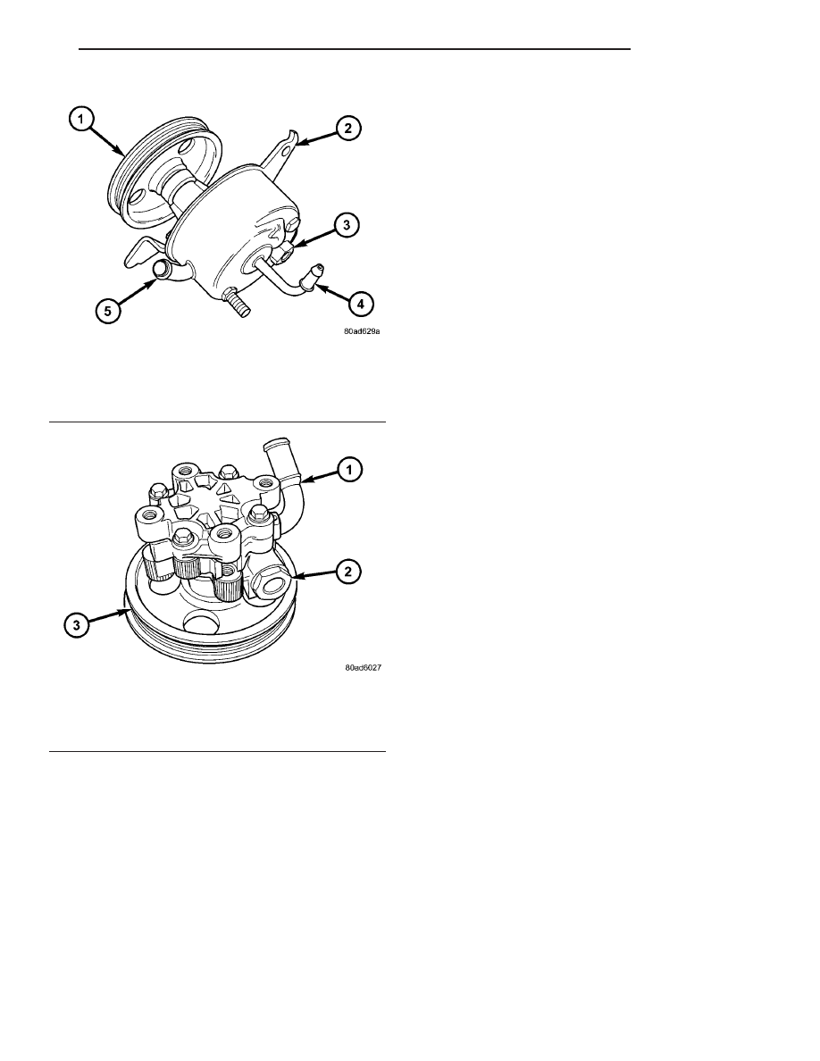
Fig. 1 POWER STEERING PUMP (2.4L)

1 - PULLEY
2 - BRACKET
3 - PRESSURE FITTING
4 - RETURN FITTING
5 - SUPPLY FITTING

Fig. 2 POWER STEERING PUMP (3.3L/3.8L)

1 - SUPPLY FITTING
2 - PRESSURE FITTING
3 - PULLEY

RS

PUMP

19 - 39

PUMP (Continued)

REMOVAL

REMOVAL - PUMP (2.4L ENGINE)

(1) Remove the (-) negative battery cable from the

battery and isolate cable.

(2) Remove the cap from the power steering fluid

reservoir.

(3) Using a siphon pump, remove as much power

steering fluid as possible from the power steering
fluid reservoir.

(4) Raise the vehicle on jack stands or centered on

a frame contact type hoist. See Hoisting in Lubrica-
tion and Maintenance.

(5) Disconnect the oxygen sensor wiring harness

from the vehicle wiring harness at the rear engine
mount bracket.

NOTE: The exhaust system needs to be removed
from the engine to allow for an area to remove the
power steering pump from the vehicle.

(6) Remove the four bolts and flag nuts securing

the catalytic converter from the exhaust manifold
(Fig. 3).

(7) Disconnect all the exhaust system isolators/

hangers from the brackets on the exhaust system (2
at the mufflers and 1 at the resonator) (Fig. 4).

(8) Remove the exhaust system by moving it as far

rearward, then lowering the front below the cross-
member and out of the vehicle.

(9) Remove the power steering fluid supply hose

from the fitting on the power steering pump. Drain
off excess power steering fluid from hose.

Fig. 3 Catalytic Converter to Exhaust Manifold

1 - CATALYTIC CONVERTER
2 - BOLT
3 - GASKET
4 - FLAG NUT

Fig. 4 Exhaust System - Typical (All Vehicles)

1 - CATALYTIC CONVERTER

4 - SUPPORT - RESONATOR

2 - BAND CLAMP

5 - RESONATOR

3 - SUPPORTS - MUFFLER

6 - MUFFLER

19 - 40

PUMP

RS

PUMP (Continued)

(10) Move the heat sleeve on the power steering

return hose to expose the hose connection at the
pump (Fig. 5). Remove the hose from the power
steering Pump. Allow the remaining power steering
fluid to drain from the power steering pump and res-
ervoir through the removed return hose.

(11) Remove the power steering fluid pressure line

from the power steering pump (Fig. 6). Drain excess
power steering fluid from tube.

(12) Remove the fasteners, then the accessory

drive splash shield.

(13) Remove the adjuster nut attaching rear of

power steering pump to the cast mounting bracket.
(Fig. 7)

Fig. 5 Pressure And Return Hoses - 2.4L

1 - POWER STEERING PUMP
2 - RETURN HOSE (HEAT SLEEVE COVERED)
3 - ROUTING CLAMPS
4 - PRESSURE HOSE TUBE NUT
5 - RETURN HOSE TUBE NUT
6 - CRADLE CROSSMEMBER
7 - POWER STEERING GEAR
8 - PRESSURE HOSE

Fig. 6 Power Steering Fluid Pressure And Return

Hose

1 - POWER STEERING FLUID RETURN HOSE
2 - POWER STEERING PUMP
3 - POWER STEERING FLUID PRESSURE HOSE

Fig. 7 Power Steering Pump Attaching Nut

1 - POWER STEERING PUMP MOUNTING BRACKET
2 - FRONT SUSPENSION CRADLE
3 - POWER STEERING PUMP
4 - ADJUSTER NUT

RS

PUMP

19 - 41

PUMP (Continued)

(14) Remove the front adjuster nut and the lower

pivot bolt (Fig. 8) attaching power steering pump
bracket to cast bracket.

(15) Remove the drive belt from the power steering

pump pulley.

(16) Remove the power steering pump and the

front bracket from the cast bracket on the engine as
an assembly through the exhaust tunnel.

(17) Remove

the

3

bolts

attaching

the

front

bracket to the power steering pump and separate the
power steering pump from the front bracket.

(18) If the power steering pump pulley needs to be

transferred, (Refer to 19 - STEERING/PUMP - DIS-
ASSEMBLY).

REMOVAL - PUMP (3.3L/3.8L ENGINE)

(1) Remove the (-) negative battery cable from the

battery and isolate cable.

(2) Remove the wiper module (unit) (Refer to 8 -

ELECTRICAL/WIPERS/WASHERS/WIPER

MOD-

ULE - REMOVAL).

(3) Raise the vehicle. (Refer to LUBRICATION &

MAINTENANCE/HOISTING - STANDARD PROCE-
DURE)

(4) Remove the drive belt splash shield.
(5) Remove the pressure hose routing bracket bolt

(Fig. 9).

(6) lower the vehicle.
(7) Remove cap from power steering fluid reser-

voir.

(8) Using a siphon pump, remove as much power

steering fluid as possible from the power steering
fluid reservoir.

(9) Disconnect the pressure hose from the pump

(Fig. 10).

(10) Disconnect the fluid supply hose from the

pump (Fig. 10).

Fig. 8 Pump Front Mounting

1 - ADJUSTER NUT
2 - PIVOT BOLT
3 - PUMP

Fig. 9 Pressure Hose Routing Clamp

1 - PRESSURE HOSE TUBE
2 - STEERING GEAR
3 - CRADLE CROSSMEMBER
4 - DRIVESHAFT
5 - ROUTING CLAMP BRACKET

Fig. 10 Supply And Pressure Hoses At Pump

1 - PRESSURE HOSE AND FITTING
2 - SUPPLY HOSE AND CLAMP
3 - POWER STEERING PUMP

19 - 42

PUMP

RS

PUMP (Continued)


Content   ..  989  990  991  992   ..