Chrysler RG Voyager. Manual - part 981


  Index      Chrysler     Chrysler RG Voyager - service repair manual 2005 year


Search            


Content   ..  979  980  981  982   ..


Chrysler RG Voyager. Manual - part 981


OPERATION

The signal represents throttle blade position. As

the position of the throttle blade changes, the resis-
tance of the TPS changes.

The PCM supplies approximately 5 volts to the

TPS. The TPS output voltage (input signal to the
powertrain control module) represents throttle blade
position. The TPS output voltage to the PCM varies
from approximately 0.6 volt at minimum throttle
opening (idle) to a maximum of 4.5 volts at wide open
throttle.

Along with inputs from other sensors, the PCM

uses the TPS input to determine current engine oper-
ating conditions. The PCM also adjusts fuel injector
pulse width and ignition timing based on these
inputs.

REMOVAL - 3.3/3.8L

(1) Disconnect the negative battery cable.
(2) Remove the electrical connector from the Inlet

Air Temperature sensor.

(3) Remove the air cleaner box lid. Remove hose

from throttle body.

(4) Disconnect the electrical connector at TPS.
(5) Disconnect the electrical connector at IAC.
(6) Remove the throttle and speed control cables

from throttle body.

(7) Remove 3 mounting bolts from throttle body.
(8) Remove throttle body.
(9) Disconnect the purge vacuum line from the

throttle body.

(10) Remove TPS from throttle body.

INSTALLATION - 3.3/3.8L

(1) Install TPS to throttle body.
(2) Disconnect the purge vacuum line from the

throttle body.

(3) Install throttle body.
(4) Install 3 mounting bolts from throttle body.

Tighten bolts.

(5) Install the throttle and speed control cables to

throttle body.

(6) Connect the electrical connector at TPS.
(7) Connect the electrical connector at IAC.
(8) Install the air cleaner box lid. Install hose to

throttle body.

(9) Install the electrical connector to the Inlet Air

Temperature sensor.

(10) Connect the negative battery cable.

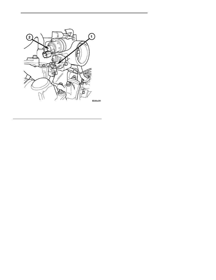
Fig. 31 Throttle Position Sensor—3.3/3.8L Engine

1 - Idle Air Control Valve
2 - Throttle Position Sensor

RS

FUEL INJECTION

14 - 41

THROTTLE POSITION SENSOR (Continued)

STEERING

TABLE OF CONTENTS

page

page

STEERING

DESCRIPTION - POWER STEERING SYSTEM

. . 1

OPERATION - POWER STEERING SYSTEM

. . . 1

DIAGNOSIS AND TESTING

DIAGNOSIS AND TESTING - POWER

STEERING SYSTEM FLOW AND
PRESSURE TEST . . . . . . . . . . . . . . . . . . . . . . 1

DIAGNOSIS AND TESTING - STEERING

SYSTEM DIAGNOSIS CHARTS . . . . . . . . . . . . 3

SPECIFICATIONS

POWER STEERING FASTENER TORQUE

. . . 10

SPECIAL TOOLS

POWER STEERING

. . . . . . . . . . . . . . . . . . . . 10

COLUMN

. . . . . . . . . . . . . . . . . . . . . . . . . . . . . . . 11

GEAR

. . . . . . . . . . . . . . . . . . . . . . . . . . . . . . . . . 27

PUMP

. . . . . . . . . . . . . . . . . . . . . . . . . . . . . . . . . 38

STEERING

DESCRIPTION - POWER STEERING SYSTEM

This vehicle comes with power steering as stan-

dard equipment. The power steering system consists
of these major components:

• POWER STEERING PUMP

• POWER STEERING GEAR

• POWER STEERING FLUID

• POWER STEERING FLUID COOLER (If

Equipped)

• POWER STEERING FLUID RESERVOIR

• POWER STEERING FLUID SUPPLY HOSE

• POWER STEERING FLUID PRESSURE HOSE

• POWER STEERING FLUID RETURN HOSE
For information on the first two components, refer

to their respective sections within this service man-
ual group. Information on all other components can
be found in POWER STEERING PUMP.

OPERATION - POWER STEERING SYSTEM

Turning of the steering wheel is converted into lin-

ear (side-to-side) travel through the meshing of the
helical pinion teeth with the rack teeth within the
steering gear. The lateral travel pushes and pulls the
tie rods to change the direction of the vehicle’s front
wheels.

Power assist steering is provided by a belt driven

rotary type pump. It directs fluid through power
steering fluid hoses to the power steering gear where
it is used to assist the driver’s turning effort.

Manual steering control of the vehicle can be main-

tained if power steering assist is lost. However,
under this condition, steering effort is significantly
increased.

DIAGNOSIS AND TESTING

DIAGNOSIS AND TESTING - POWER STEERING
SYSTEM FLOW AND PRESSURE TEST

ALL ENGINES

The following procedure is to be used to test the

operation of the power steering system on this vehi-
cle. This test will provide the flow rate of the power
steering pump along with the maximum relief pres-
sure. This test is to be performed to determine if the
power steering pump or power steering gear is not
functioning properly. The following flow and pressure
test is performed using the Power Steering Analyzer
Kit, Special Tool 6815 (Fig. 1), hoses, Special Tools
6905 and 6959, and fittings from adapter kit, Special
Tool 6893.

Fig. 1 Power Steering Analyzer With Hoses Installed

1 - OUTLET
2 - SPECIAL TOOL 6815
3 - INLET

RS

STEERING

19 - 1

Assemble hoses on Power Steering Analyzer, Spe-

cial Tool 6815, as shown. Install Pressure Hose, Spe-
cial Tool 6905 (in 6893 kit), in the inlet fitting on
Power Steering Analyzer. Install Pressure Hose, Spe-
cial Tool 6713 (in 6815 kit) on Pressure Hose, Special
Tool 6905. Install Pressure Hose, Special Tool 6959,
in the outlet fitting on Power Steering Analyzer.

Install the following adapters from Adapter Set,

Special Tool 6893 (Fig. 2), on the analyzer hose ends:
Install Adapter Fitting, Special Tool 6844, on Pres-
sure Hose, Special Tool 6713. Install Adapter Fitting,
Special Tool 6826, on Pressure Hose, Special Tool
6959.

CAUTION: To prevent personal injury, safety gog-
gles should be worn at all times when performing
any test procedures on the power steering pump or
power steering gear.

The following procedure is to be used to test the

operation of the power steering system on the vehi-
cle.

(1) Check belt tension and adjust as necessary.
(2) Disconnect the power steering fluid pressure

hose from the power steering pump (Fig. 3) (Fig. 4).

(3) Connect Adapter Fitting, Special Tool 6844,

attached to pressure hose from inlet (gauge end) of
Power Steering Analyzer to the pressure fitting on
the power steering pump.

(4) Connect vehicle power steering fluid pressure

hose to Adapter Fitting, Special Tool 6826, which
should be already installed in the outlet hose (valve
end) of Power Steering Analyzer.

NOTE: During the next few steps, do not steer vehi-
cle as air will be forced into the steering gear.

(5) Completely open valve on Power Steering Ana-

lyzer.

Fig. 2 Power Steering Analyzer Adapters 6893

Fig. 3 Pressure Hose Connection To Power Steering

Pump - 2.4L Engine

1 - POWER STEERING FLUID RETURN HOSE
2 - POWER STEERING PUMP
3 - POWER STEERING FLUID PRESSURE HOSE

Fig. 4 Supply & Pressure Hoses At Pump - 3.3L/3.8L

Engine

1 - PRESSURE HOSE AND FITTING
2 - SUPPLY HOSE AND CLAMP
3 - POWER STEERING PUMP

19 - 2

STEERING

RS

STEERING (Continued)


Content   ..  979  980  981  982   ..