Chrysler RG Voyager. Manual - part 970


  Index      Chrysler     Chrysler RG Voyager - service repair manual 2005 year


Search            


Content   ..  968  969  970  971   ..


Chrysler RG Voyager. Manual - part 970


REMOVAL

The front cradle crossmember must be installed in

the design location to achieve proper front end sus-
pension alignment. If the cradle crossmember is
removed without applying reference marks on the
frame rails, align the cradle crossmember according
to the dimensions provided in this group.

NOTE: If the caged nuts in the frame rails become
damaged and cannot be reused, a replacement nut
can be obtained through Mopar

T

(Fig. 20).

REMOVAL

(1) Disconnect battery negative cable.
(2) Remove steering column lower cover from

instrument panel (Refer to 23 - BODY/INSTRU-
MENT

PANEL/STEERING

COLUMN

OPENING

COVER - REMOVAL).

(3) Remove steering column cover backing plate

(Refer to 23 - BODY/INSTRUMENT PANEL/STEER-
ING

COLUMN

COVER

BACKING

PLATE

-

REMOVAL).

(4) Position steering so front wheels are straight

ahead.

CAUTION: Do not rotate steering wheel after disen-
gaging lower coupling from steering gear, damage
to air bag clock spring can result.

(5) Remove clinch bolt attaching steering column

coupling to steering gear shaft (Fig. 21).

(6) Remove steering column coupling from tele-

scoping steering gear shaft.

(7) Hoist vehicle and support on safety stands.
(8) Position a drain pan under power steering

pump and oil return hose coupling.

(9) Using a hose pinch-off pliers (C-4390), pinch

power steering oil return hose off between the cross-
member coupling and the pump.

(10) Loosen hose clamp at the cradle crossmember

coupling.

(11) Disconnect return hose from metal tube.
(12) While holding pressure relief valve nut on

back of power steering pump, Remove flare nut
attaching high pressure hose to back of pump.

(13) Remove high pressure hose from pump.
(14) Allow power steering fluid to drain into pan.
(15) Remove bolts attaching anti-lock brake sensor

leads to cradle crossmember.

(16) Position anti-lock brake leads out of the way.
(17) Disconnect stabilizer bar links from ends of

stabilizer bar.

(18) Disconnect lower ball joints from lower steer-

ing knuckles (Refer to 2 - SUSPENSION/FRONT/
LOWER BALL JOINT - REMOVAL).

(19) Remove the rear engine mount heat shield

(Fig. 22).

(20) Remove through bolt attaching rear engine

mount to cradle crossmember (Fig. 23).

(21) Using paint or grease pencil, mark outline of

cradle crossmember on frame rails to aid installation.

(22) Support cradle crossmember on suitable lift-

ing device (Fig. 25).

(23) Remove bolts attaching crossmember to front

frame rails (Fig. 24).

(24) Remove cradle crossmember from vehicle (Fig.

25).

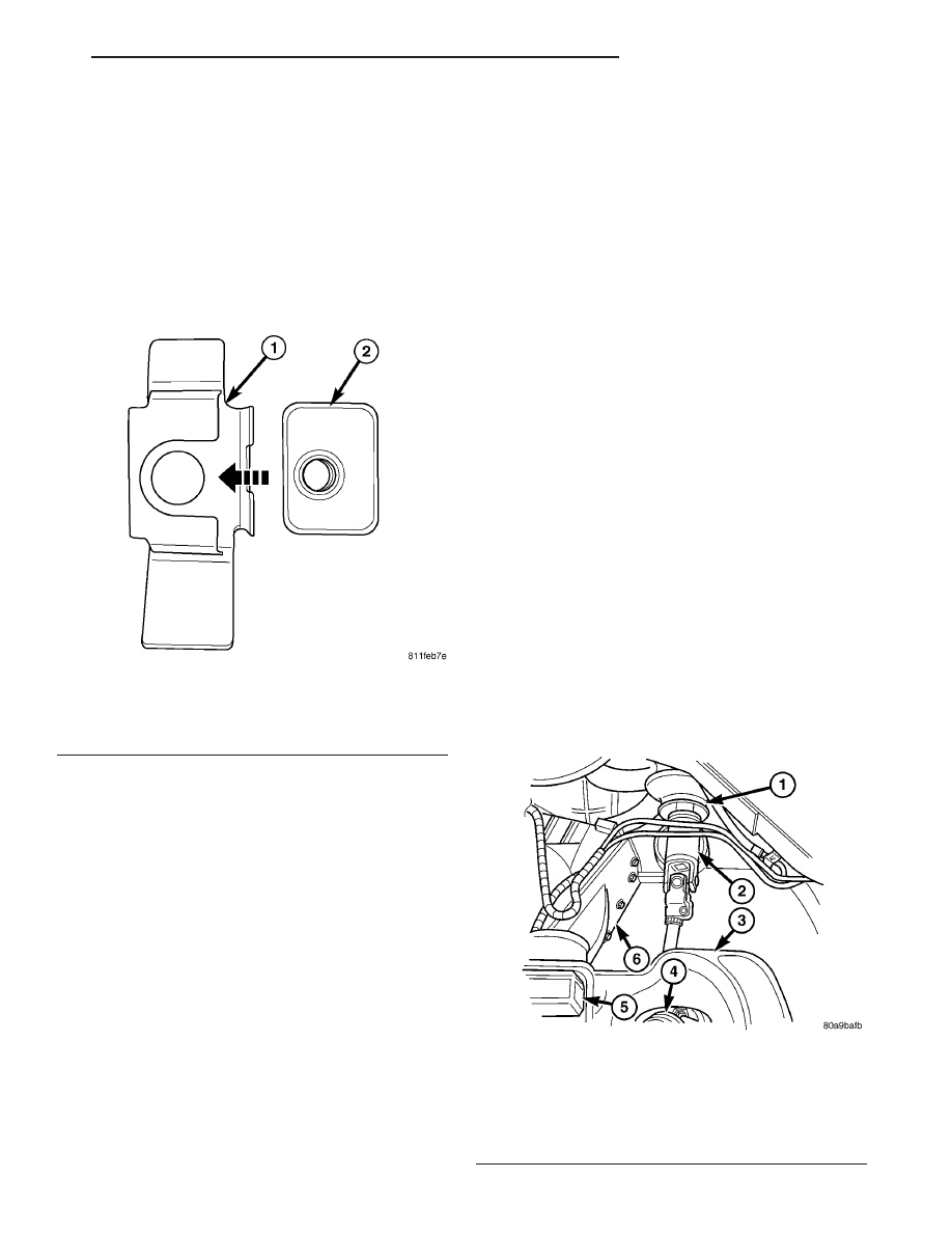
Fig. 20 FRONT CRADLE CROSSMEMBER CAGED

NUT

1 - BRACKET
2 - CAGED NUT

Fig. 21 STEERING COUPLING

1 - STEERING SHAFT BOOT
2 - STEERING SHAFT
3 - CROSSMEMBER
4 - STEERING GEAR
5 - MOUNT
6 - TRANSAXLE

RS

FRAME & BUMPERS

13 - 17

FRONT CRADLE CROSSMEMBER (Continued)

INSTALLATION

NOTE: If cradle crossmember requires replacement.
Refer to Group 2, Suspension, to transfer suspen-
sion components and Group 19, Steering, to trans-
fer steering components.

(1) Support crossmember on suitable lifting device

(Fig. 25).

(2) Position crossmember to vehicle.
(3) Loosely install bolts attaching cradle cross-

member to front frame rails.

(4) Place upper half of bushing on top of cross-

member aligned to receive square tube protruding
upward from lower bushing half.

(5) Align crossmember to previously made marks

on frame rails.

(6) Tighten bolts attaching cradle crossmember to

frame rails.

(7) Install through bolt attaching rear engine

mount to cradle crossmember (Fig. 23) and tighten to
68 N·m (50 ft. lbs.) torque.

(8) Install the rear mount heat shield (Fig. 22).
(9) Connect lower ball joints to steering knuckles

(Refer to 2 - SUSPENSION/FRONT/LOWER BALL
JOINT - INSTALLATION)

(10) Connect stabilizer bar links to ends of stabi-

lizer bar.

(11) Install bolts attaching anti-lock brake sensor

leads to cradle crossmember.

(12) Install high pressure hose to pump.
(13) Connect return hose to metal tube.
(14) Tighten hose clamp at the cradle crossmember

coupling.

(15) Remove pinch-off pliers.
(16) Position steering so front wheels are straight

ahead.

(17) Install steering column coupling to telescoping

steering gear shaft.

(18) Install clinch bolt attaching steering column

coupling to steering gear shaft.

(19) Install steering column cover backing plate

(Refer to 23 - BODY/INSTRUMENT PANEL/STEER-
ING

COLUMN

COVER

BACKING

PLATE

-

INSTALLATION)

(20) Install steering column lower cover from

instrument panel (Refer to 23 - BODY/INSTRU-

Fig. 22 REAR MOUNT HEAT SHIELD

1 - BOLT
2 - HEAT SHIELD
3 - CLIP
4 - REAR ENGINE MOUNT

Fig. 23 REAR MOUNT

1 - BOLT
2 - REAR MOUNT BRACKET
3 - THROUGH BOLT
4 - REAR MOUNT

Fig. 24 CRADLE CROSSMEMBER MOUNT

1 - CROSSMEMBER MOUNT
2 - BRAKE HOSE MOUNT
3 - STEERING TIE ROD
4 - FRONT CROSSMEMBER
5 - FRAME RAIL

13 - 18

FRAME & BUMPERS

RS

FRONT CRADLE CROSSMEMBER (Continued)

MENT

PANEL/STEERING

COLUMN

OPENING

COVER - INSTALLATION).

(21) Connect battery negative cable.

FRONT CROSSMEMBER
MOUNT BUSHINGS

REMOVAL

(1) Using paint or grease pencil, mark outline of

cradle crossmember on frame rails.

(2) Loosen bolts attaching crossmember to frame

rails.

(3) Remove bolt on bushing that requires replace-

ment.

(4) Allow cradle crossmember to drop down enough

to gain clearance for bushing removal.

(5) Remove bushing from vehicle.

INSTALLATION

(1) Apply rubber lubrication or soap to replace-

ment bushing.

(2) Insert lower half of bushing into square hole in

cradle crossmember.

(3) Place upper half of bushing on top of cross-

member aligned to receive square tube protruding
upward from lower bushing half.

(4) Squeeze bushing halves together to ensure they

are properly mated.

(5) Lift cradle crossmember upward to close gap

between the bushing and frame.

(6) Verify that lower bushing is fully seated into

cradle crossmember and upper bushing.

(7) Install bolt attaching bushing and crossmember

to frame rail hand tight.

(8) Align cradle crossmember to reference marks

on frame rails.

(9) Tighten cradle crossmember to frame rails

attaching bolts to 163 N·m (120 ft. lbs.) torque.

Fig. 25 CRADLE CROSSMEMBER

1 - ENGINE OIL PAN
2 - TRANSAXLE
3 - LOWER CONTROL ARM

4 - FRONT CROSSMEMBER
5 - LIFT DEVICE
6 - SPINDLE

RS

FRAME & BUMPERS

13 - 19

FRONT CRADLE CROSSMEMBER (Continued)


Content   ..  968  969  970  971   ..