Chrysler RG Voyager. Manual - part 962


  Index      Chrysler     Chrysler RG Voyager - service repair manual 2005 year


Search            


Content   ..  960  961  962  963   ..


Chrysler RG Voyager. Manual - part 962


(7) Inspect and clean manifold. (Refer to 9 -

ENGINE/MANIFOLDS/EXHAUST

MANIFOLD

-

INSPECTION) (Refer to 9 - ENGINE/MANIFOLDS/
EXHAUST MANIFOLD - CLEANING)

CLEANING

(1) Discard gasket (if equipped) and clean all sur-

faces of manifold and cylinder head.

INSPECTION

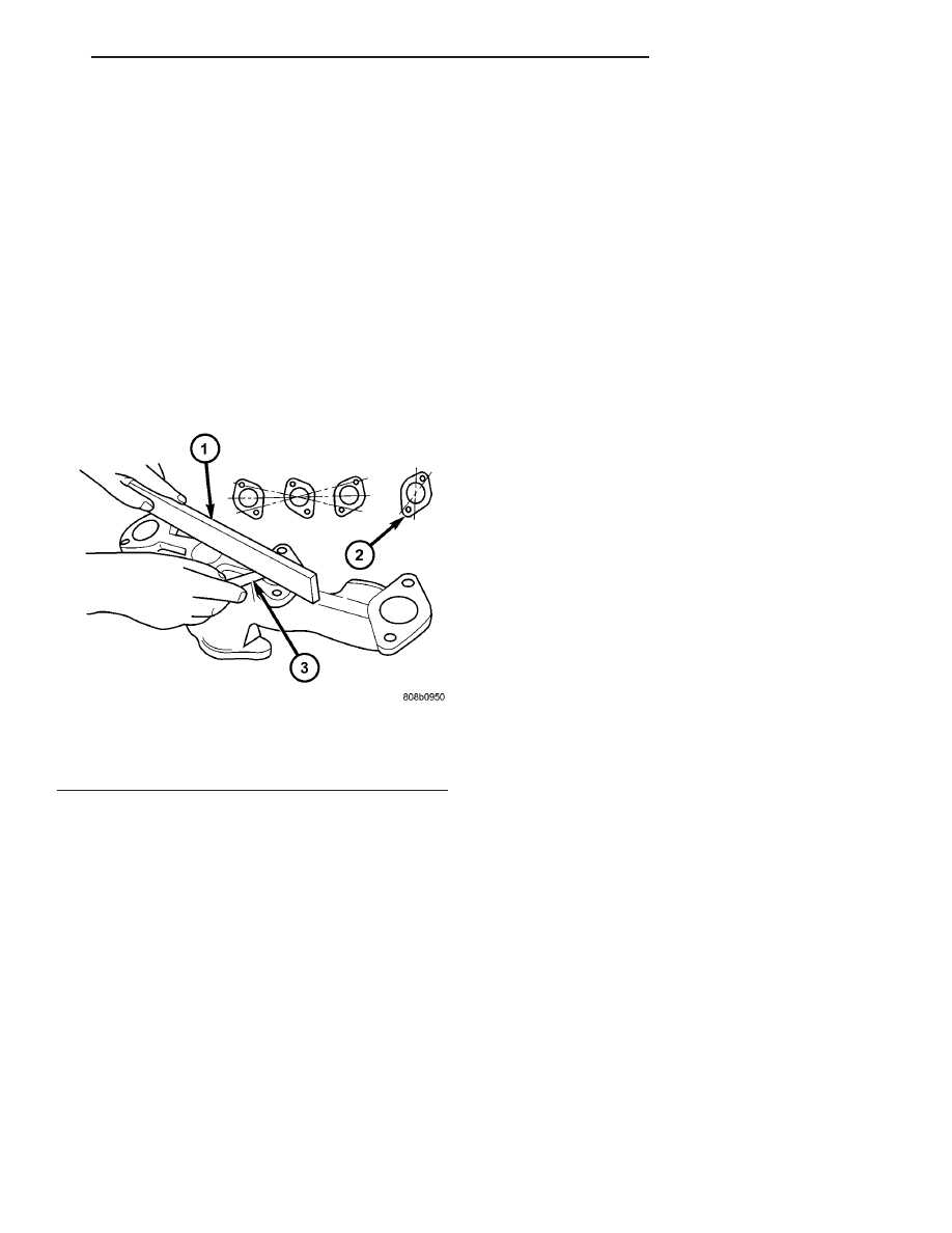
Inspect exhaust manifolds for damage or cracks

and check distortion of the cylinder head mounting
surface and exhaust crossover mounting surface with
a straightedge and thickness gauge (Fig. 135).

Manifold surface flatness limits should not exceed

1.0 mm (0.039 in.).

INSTALLATION

(1) Position exhaust manifold on cylinder head

(Fig. 134). Install bolts to center runner (cylinder #4)
and initial tighten to 2.8 N·m (25 in. lbs.).

(2) Using a new gasket, attach crossover pipe to

exhaust manifold and tighten bolts to 41 N·m (30 ft.
lbs.) (Fig. 133).

NOTE: Inspect crossover pipe fasteners for damage
from heat and corrosion. The cross-over bolts are
made of a special stainless steel alloy. If replace-
ment is required, OEM bolts are highly recom-
mended.

(3) Position heat shield on manifold (Fig. 134).
(4) Install the remaining manifold attaching bolts.

Tighten all bolts to 23 N·m (200 in. lbs.).

(5) Install and tighten heat shield attaching nut to

12 N·m (105 in. lbs.) (Fig. 134).

(6) Connect battery negative cable.

VALVE TIMING

STANDARD PROCEDURE

STANDARD PROCEDURE - VALVE TIMING
VERIFICATION

(1) Remove front cylinder head cover and all 6

spark plugs.

(2) Rotate engine until the #2 piston is at TDC of

the compression stroke.

(3) Install a degree wheel on the crankshaft pulley.
(4) With proper adaptor, install a dial indicator

into #2 spark plug hole. Using the indicator find TDC
on the compression stroke.

(5) Position the degree wheel to zero.
(6) Remove dial indicator from spark plug hole.
(7) Place a 5.08 mm (0.200 in.) spacer between the

valve stem tip of #2 intake valve and rocker arm pad.
Allow tappet to bleed down to give a solid tappet
effect.

(8) Install a dial indicator so plunger contacts the

#2 intake valve spring retainer as nearly perpendic-
ular as possible. Zero the indicator.

(9)

Rotate the engine clockwise until the intake

valve has lifted .254 mm (0.010 in.).

CAUTION: Do not turn crankshaft any further clock-
wise as intake valve might bottom and result in
serious damage.

(10) Degree wheel should read 6 degrees BTDC to

6 degrees ATDC.

STANDARD PROCEDURE - MEASURING
TIMING CHAIN WEAR

NOTE: This procedure must be performed with the
timing chain cover removed (Refer to 9 - ENGINE/
VALVE TIMING/TIMING CHAIN COVER - REMOVAL).

(1) Position a scale next to timing chain so that

any movement of chain may be measured (Fig. 136).

(2) Position a torque wrench and socket on the

camshaft sprocket attaching bolt. Apply force in the
direction of crankshaft rotation to take up slack to
the following torque:

• 41 N·m (30 ft. lb.) with cylinder heads installed

• 20 N·m (15 ft. lb.) with cylinder heads removed

NOTE:

With

torque

applied

to

the

camshaft

sprocket bolt, crankshaft should not be permitted to
move. It may be necessary to block crankshaft to
prevent rotation.

Fig. 135 Check Exhaust Manifold Mounting

1 - STRAIGHT EDGE
2 - CROSSOVER PIPE MOUNTING SURFACE
3 - FEELER GAUGE

RS

ENGINE 3.3/3.8L

9 - 157

EXHAUST MANIFOLD - LEFT (Continued)

(3) Holding a measuring scale along edge of chain

links (Fig. 136).

(4) Apply force in the reverse direction to the fol-

lowing torque:

• 41 N·m (30 ft. lb.) with cylinder heads installed

• 20 N·m (15 ft. lb.) with cylinder heads removed
(5) Measure amount of sprocket/chain movement.
(6) Install a new timing chain and sprockets if

movement exceeds 3.175 mm (1/8 in.).

TIMING CHAIN COVER

REMOVAL

(1) Disconnect negative cable from battery.
(2) Drain cooling system. (Refer to 7 - COOLING -

STANDARD PROCEDURE)

(3) Raise vehicle on hoist.
(4) Drain engine oil.
(5) Remove right wheel and inner splash shield.
(6) Remove oil pan. (Refer to 9 - ENGINE/LUBRI-

CATION/OIL PAN - REMOVAL)

(7) Remove oil pick-up tube (Fig. 137).
(8) Remove accessory drive belt. (Refer to 7 -

COOLING/ACCESSORY

DRIVE/DRIVE

BELTS

-

REMOVAL)

(9) Remove A/C compressor and set aside.
(10) Remove crankshaft vibration damper. (Refer

to

9

-

ENGINE/ENGINE

BLOCK/VIBRATION

DAMPER - REMOVAL)

(11) Remove radiator lower hose.
(12) Remove heater hose from timing chain cover

housing (Fig. 138) or water pump inlet tube (if
engine oil cooler equipped) (Fig. 139).

(13) Remove the right side engine mount. (Refer to

9 - ENGINE/ENGINE MOUNTING/RIGHT MOUNT
- REMOVAL)

(14) Remove idler pulley from engine bracket (Fig.

140).

(15) Remove the engine mount bracket (Fig. 140).

Fig. 136 Measuring Timing Chain Wear

1 - TORQUE WRENCH

Fig. 137 OIL PICKUP TUBE

1 - BOLT
2 - OIL PICK-UP TUBE
3 - O-RING

Fig. 138 HEATER RETURN HOSE (Without Engine

Oil Cooler)

1 - CAP AND CLAMP (OIL COOLER EQUIPPED ONLY)
2 - HOSE ASSEMBLY - HEATER RETURN
3 - BOLT - HEATER TUBE ATTACHING
4 - BOLT - HEATER TUBE ATTACHING

9 - 158

ENGINE 3.3/3.8L

RS

VALVE TIMING (Continued)

(16) Remove camshaft position sensor from timing

chain cover (Fig. 140).

(17) Remove the water pump for cover removal

clearance. (Refer to 7 - COOLING/ENGINE/WATER
PUMP - REMOVAL)

(18) Remove the bolt attaching the power steering

pump support strut to the front cover (Fig. 141).

(19) Remove the timing chain cover fasteners.

Remove timing chain cover (Fig. 142).

INSTALLATION

(1) Be sure mating surfaces of chain case cover

and cylinder block are clean and free from burrs.
Crankshaft oil seal must be removed to insure cor-
rect oil pump engagement.

NOTE: DO NOT USE SEALER ON COVER GASKET

(2) Position new gasket on timing cover (Fig. 142).

Adhere new gasket to chain case cover, making sure
that the lower edge of the gasket is flush to 0.5 mm
(0.020 in.) passed the lower edge of the cover.

(3) Rotate crankshaft so that the oil pump drive

flats are in the vertical position.

(4) Position oil pump inner rotor so the mating

flats are in the same position as the crankshaft drive
flats (Fig. 142).

CAUTION: Make sure the oil pump is engaged on
the crankshaft correctly or severe damage may
result.

(5) Install timing cover (Fig. 142).
(6) Install timing chain cover bolts. Tighten M8

bolts to 27 N·m (20 ft. lbs.) and M10 bolts to 54 N·m
(40 ft. lbs.) (Fig. 143).

(7) Install crankshaft front oil seal. (Refer to 9 -

ENGINE/ENGINE

BLOCK/CRANKSHAFT

OIL

SEAL - FRONT - INSTALLATION)

Fig. 139 HEATER HOSES 3.3/3.8L (With Engine Oil

Cooler)

1 - HOSE - HEATER SUPPLY
2 - HOSE - HEATER RETURN
3 - TUBE ASSEMBLY - HEATER RETURN
4 - BOLT - TUBE ASSEMBLY
5 - BOLT - TUBE ASSEMBLY
6 - HOSE - HEATER RETURN/OIL COOLER OUTLET

Fig. 140 Engine Mount Bracket

1 - CAMSHAFT SENSOR
2 - BOLT - CAMSHAFT SENSOR
3 - BOLT - MOUNT BRACKET (VERTICAL)
4 - BRACKET - ENGINE MOUNT
5 - BOLT - MOUNT BRACKET (HORIZONTAL)
6 - PULLEY - IDLER
7 - BOLT - IDLER PULLEY
8 - SPACER - IDLER PULLEY BOLT
9 - BOLT - MOUNT BRACKET (HORIZONTAL)

Fig. 141 Power Steering Pump Strut

1 - BOLT - LOWER
2 - STRUT - P/S PUMP
3 - BOLT - UPPER

RS

ENGINE 3.3/3.8L

9 - 159

TIMING CHAIN COVER (Continued)

(8) Install water pump and pulley. (Refer to 7 -

COOLING/ENGINE/WATER PUMP - INSTALLA-
TION)

(9) Install crankshaft vibration damper. (Refer to 9

- ENGINE/ENGINE BLOCK/VIBRATION DAMPER -
INSTALLATION)

(10) Install engine mount bracket (Fig. 140) and

tighten M10 to 54 N·m (40 ft. lbs.), M8 bolt to 28
N·m (21 ft. lb. lbs.).

(11) Install idler pulley on engine mount bracket

(Fig. 140).

(12) Install right side engine mount. (Refer to 9 -

ENGINE/ENGINE MOUNTING/RIGHT MOUNT -
INSTALLATION)

(13) Install camshaft position sensor (Refer to 8 -

ELECTRICAL/IGNITION

CONTROL/CAMSHAFT

POSITION SENSOR - INSTALLATION).

Fig. 142 Timing Chain Cover and Gasket

1 - GASKET
2 - TIMING CHAIN COVER

Fig. 143 TIMING CHAIN COVER BOLT LOCATIONS

1 - BOLT - M8 x 1.25 x 95

4 - BOLT - M8 x 1.25 x 80

2 - BOLT - M10 x 1.5 x 100

5 - BOLT - M8 x 1.25 x 45

3 - BOLT - M10 x 1.5 x 85

9 - 160

ENGINE 3.3/3.8L

RS

TIMING CHAIN COVER (Continued)


Content   ..  960  961  962  963   ..