Chrysler RG Voyager. Manual - part 961


  Index      Chrysler     Chrysler RG Voyager - service repair manual 2005 year


Search            


Content   ..  959  960  961  962   ..


Chrysler RG Voyager. Manual - part 961


(9) Remove radiator upper hose.
(10) Remove the intake manifold bolts.
(11) Remove lower intake manifold (Fig. 125).

WARNING: INTAKE MANIFOLD GASKET IS MADE
OF VERY THIN METAL AND MAY CAUSE PER-
SONAL INJURY, HANDLE WITH CARE.

(12) Remove intake manifold seal retainers screws

(Fig. 125). Remove intake manifold gasket.

(13) Inspect and clean manifold. (Refer to 9 -

ENGINE/MANIFOLDS/INTAKE

MANIFOLD

-

INSPECTION) (Refer to 9 - ENGINE/MANIFOLDS/
INTAKE MANIFOLD - CLEANING)

CLEANING

(1) Discard gasket(s).
(2) Clean all sealing surfaces.

INSPECTION

Check for:
• Damage and cracks of each section.

• Clogged water passages in end cross-overs (if

equipped).

• Check for cylinder head mounting surface distor-

tion using a straightedge and thickness gauge. (Refer
to 9 - ENGINE/CYLINDER HEAD - INSPECTION)

INSTALLATION - LOWER INTAKE MANIFOLD

(1) Place a bead (approximately 1/4 in. diameter)

of Mopar

t Engine RTV GEN II onto each of the four

manifold to cylinder head gasket corners (Fig. 126).

(2) Carefully install the new intake manifold gas-

ket (Fig. 125). Tighten end seal retainer screws to 12
N·m (105 in. lbs.).

(3) Install lower intake manifold (Fig. 125). Install

the bolts and torque to 1 N·m (10 in. lbs.). Then
torque bolts to 22 N·m (200 in. lbs.) in sequence
shown in (Fig. 127). Then torque again to 22 N·m
(200 in. lbs.). After intake manifold is in place,
inspect to make sure seals are in place.

(4) Install the fuel injectors and rail assembly.

(Refer to 14 - FUEL SYSTEM/FUEL DELIVERY/
FUEL RAIL - INSTALLATION)

(5) Connect fuel injector electrical harness.
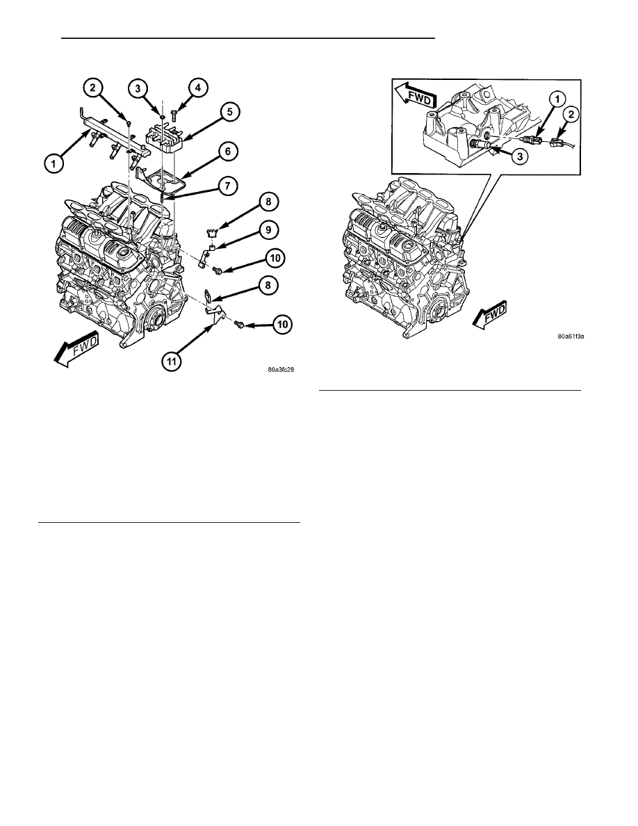
(6) Connect the engine coolant temperature sensor

(Fig. 124).

(7) Connect the heater supply (Fig. 124) and radi-

ator upper hoses to manifold.

Fig. 123 FUEL RAIL AND IGNITION COIL &

BRACKET

1 - FUEL RAIL
2 - BOLT - FUEL RAIL
3 - NUT - IGNITION COIL
4 - BOLT - IGNITION COIL
5 - IGNITION COIL
6 - BRACKET - IGNITION COIL
7 - STUD - IGNITION COIL
8 - SEPARATOR - SPARK PLUG CABLE
9 - BRACKET - SPARK PLUG CABLE SEPARATOR
10 - BOLT - SEPARATOR BRACKET
11 - BRACKET - SPARK PLUG CABLE SEPARATOR

Fig. 124 ECT SENSOR & HEATER SUPPLY

1 - ENGINE COOLANT TEMPERATURE SENSOR
2 - CONNECTOR - ENGINE COOLANT SENSOR
3 - FITTING - HEATER SUPPLY

RS

ENGINE 3.3/3.8L

9 - 153

INTAKE MANIFOLD - LOWER (Continued)

(8) Connect the fuel line. (Refer to 14 - FUEL SYS-

TEM/FUEL

DELIVERY/QUICK

CONNECT

FIT-

TING - STANDARD PROCEDURE)

(9) Install the upper intake manifold. (Refer to 9 -

ENGINE/MANIFOLDS/INTAKE

MANIFOLD

-

INSTALLATION)

(10) Connect negative battery cable.
(11) Fill the cooling system. (Refer to 7 - COOL-

ING - STANDARD PROCEDURE)

EXHAUST MANIFOLD - RIGHT

REMOVAL

(1) Disconnect battery negative cable.
(2) Remove the wiper module. (Refer to 8 - ELEC-

TRICAL/WIPERS/WASHERS/WIPER

MODULE

-

REMOVAL)

(3) Disconnect spark plug wires.
(4) Remove

bolts

fastening

crossover

pipe

to

exhaust manifold (Fig. 128).

Fig. 125 INTAKE MANIFOLD - LOWER

1 - INTAKE MANIFOLD - LOWER
2 - BOLT - GASKET END SEAL RETAINER
3 - GASKET
4 - BOLT - LOWER INTAKE MANIFOLD

Fig. 126 Intake Manifold Gasket Sealing

1 - SEALER LOCATIONS

Fig. 127 LOWER MANIFOLD TIGHTENING

SEQUENCE

Fig. 128 CROSS-OVER PIPE

1 - CROSS-OVER PIPE
2 - BOLT
3 - GASKET
4 - FLAG NUT

9 - 154

ENGINE 3.3/3.8L

RS

INTAKE MANIFOLD - LOWER (Continued)

(5) Disconnect and remove the upstream oxygen

sensor (Fig. 131).

(6) Remove the heat shield attaching screws (Fig.

131).

(7) Remove the upper heat shield (Fig. 131).
(8) Raise vehicle on hoist and remove drive belt

shield.

(9) Loosen the power steering pump support strut

lower bolt (Fig. 129).

(10) Disconnect downstream oxygen sensor connec-

tor.

(11) Disconnect

catalytic

converter

pipe

from

exhaust manifold (Fig. 130).

(12) Lower vehicle and remove the power steering

pump support strut upper bolt (Fig. 129).

(13) Remove bolts attaching exhaust manifold to

cylinder head and remove manifold (Fig. 131).

(14) Inspect and clean manifold. (Refer to 9 -

ENGINE/MANIFOLDS/EXHAUST

MANIFOLD

-

CLEANING) (Refer to 9 - ENGINE/MANIFOLDS/
EXHAUST MANIFOLD - INSPECTION)

CLEANING

(1) Discard gasket (if equipped) and clean all sur-

faces of manifold and cylinder head.

INSPECTION

Inspect exhaust manifolds for damage or cracks

and check distortion of the cylinder head mounting
surface and exhaust crossover mounting surface with
a straightedge and thickness gauge (Fig. 132).

Manifold surface flatness limits should not exceed

1.0 mm (0.039 in.).

INSTALLATION

(1) Position exhaust manifold on cylinder head and

install bolts to center runner (cylinder #3) and initial
tighten to 2.8 N·m (25 in. lbs.) (Fig. 131)

Fig. 129 P/S PUMP STRUT

1 - BOLT - LOWER
2 - STRUT - P/S PUMP
3 - BOLT - UPPER

Fig. 130 Catalytic Converter to Exhaust Manifold

1 - FLAG NUT
2 - GASKET
3 - BOLT
4 - CATALYTIC CONVERTER

Fig. 131 EXHAUST MANIFOLD - RIGHT

1 - SCREW - HEAT SHIELD
2 - HEAT SHIELD - UPPER
3 - BOLT - EXHAUST MANIFOLD
4 - HEAT SHIELD - LOWER
5 - EXHAUST MANIFOLD - RIGHT
6 - OXYGEN SENSOR - UPSTREAM

RS

ENGINE 3.3/3.8L

9 - 155

EXHAUST MANIFOLD - RIGHT (Continued)

(2) Using a new gasket, attach crossover pipe to

exhaust manifold and tighten bolts to 41 N·m (30 ft.
lbs.) (Fig. 128).

NOTE: Inspect crossover pipe fasteners for damage
from heat and corrosion. The cross-over bolts are
made of a special stainless steel alloy. If replace-
ment is required, OEM bolts are highly recom-
mended.

(3) Install the remaining manifold attaching bolts.

Tighten all bolts to 23 N·m (200 in. lbs.).

(4) Position the power steering pump support strut

and install upper bolt (Fig. 129).

(5) Install heat shield and attaching screws (Fig.

131).

(6) Install and connect upstream oxygen sensor

(Fig. 131).

(7) Raise the vehicle.
(8) Attach catalytic converter pipe to exhaust man-

ifold using new gasket and tighten bolts to 37 N·m
(27 ft. lbs.) (Fig. 130).

(9) Connect downstream oxygen sensor connector.
(10) Tighten the power steering pump support

strut lower bolt (Fig. 129).

(11) Install the belt splash shield and lower the

vehicle.

(12) Install the wiper module. (Refer to 8 - ELEC-

TRICAL/WIPERS/WASHERS/WIPER

MODULE

-

INSTALLATION)

(13) Connect battery negative cable.

EXHAUST MANIFOLD - LEFT

REMOVAL

(1) Disconnect battery negative cable.
(2) Remove

bolts

attaching

crossover

pipe

to

exhaust manifold (Fig. 133).

(3) Disconnect left cylinder bank spark plug wires.
(4) Remove heat shield attaching bolts (Fig. 134).
(5) Remove bolts attaching exhaust manifold to

cylinder head (Fig. 134).

(6) Remove the exhaust manifold (Fig. 134).

Fig. 132 Check Exhaust Manifold Mounting

1 - STRAIGHT EDGE
2 - CROSSOVER PIPE MOUNTING SURFACE
3 - FEELER GAUGE

Fig. 133 CROSS-OVER PIPE

1 - CROSS-OVER PIPE
2 - BOLT
3 - GASKET
4 - FLAG NUT

Fig. 134 EXHAUST MANIFOLD - LEFT

1 - EXHAUST MANIFOLD - LEFT BANK
2 - HEAT SHIELD
3 - NUT - HEAT SHIELD
4 - BOLT - EXHAUST MANIFOLD

9 - 156

ENGINE 3.3/3.8L

RS

EXHAUST MANIFOLD - RIGHT (Continued)


Content   ..  959  960  961  962   ..