Chrysler RG Voyager. Manual - part 753


  Index      Chrysler     Chrysler RG Voyager - service repair manual 2005 year


Search            


Content   ..  751  752  753  754   ..


Chrysler RG Voyager. Manual - part 753


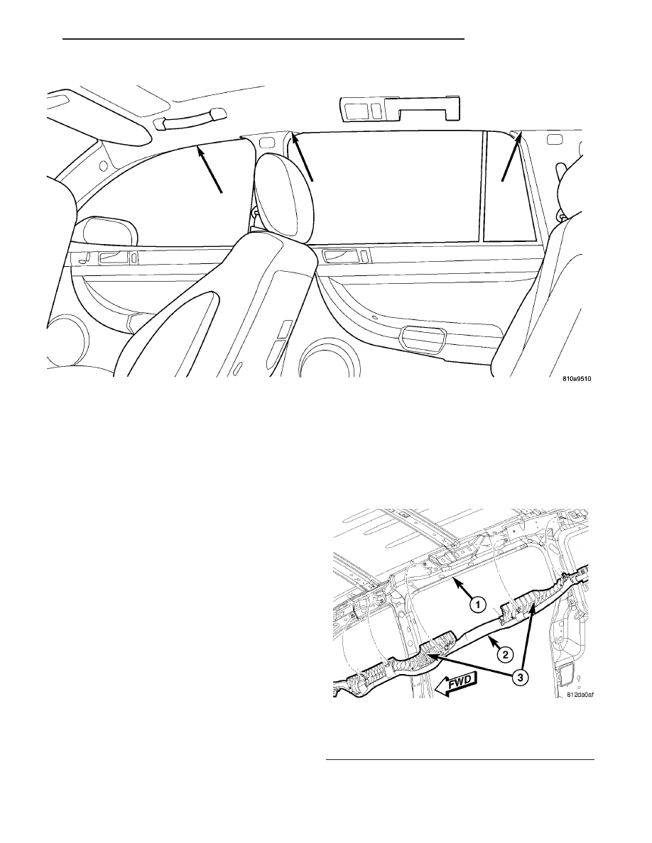
wrap that extends along the roof rail from the A-pil-
lar at the front of the vehicle to just behind the
D-pillar at the rear of the vehicle. One tether extends
down the A-pillar from the front of the airbag cush-
ion, and a second tether extends to the roof rail at
the D-pillar. The end of the A-pillar tether is secured
to a slot in the sheet metal with a metal hook
retained by a bolt. The D-pillar tether is attached to
the d-pillar.

The hybrid-type inflator for each airbag is secured

to the roof rail just behind the C-pillar. The inflator
bracket and the airbag cushion are secured with both
plastic push-in fasteners and screws to the roof rail.
A short pigtail wire harness connects the curtain air-
bag inflator to the body wire harness.

The curtain airbag cannot be adjusted or repaired

and must be replaced if deployed, faulty, or in any
way damaged. Once a curtain airbag has been
deployed, the complete airbag unit (Refer to 8 -
ELECTRICAL/RESTRAINTS - STANDARD PROCE-
DURE - SERVICE AFTER AN AIRBAG DEPLOY-
MENT), headliner, upper A/B/C and D-pillar trim,
and all other visibly damaged components must be
replaced (Refer to Section 23 - BODY/INTERIOR for
complete body interior Removal and Installation pro-
cedures). Refer to the appropriate diagnostic informa-
tion for complete diagnosis and testing or the curtain
airbags.

The curtain airbags also contain Head Impact

Counter Measures (Fig. 14). These injection molded

plastic components help to reduce the likelihood of
injury or death in the event of a side impact event.
They are attached to the curtain airbag and are also
used to mount the curtain to the inside roof rail.
Their purpose is to maintain a flat surface in which
the deployed airbag to be pressed against when inte-
rior occupants/forces are pushing outwards.

Fig. 13 CURTAIN AIRBAG LOCATION - TYPICAL

Fig. 14 HEAD IMPACT COUNTER MEASURES

1 - SLIDING DOOR OPENING/ROOF RAIL
2 - CURTIAN AIRBAG
3 - HEAD IMPACT COUNTER MEASURES

RS

RESTRAINTS

8O - 13

CURTAIN AIRBAG (Continued)

OPERATION

Each curtain airbag is deployed individually by an

electrical signal generated by the Occupant Restraint
Controller (ORC) to which it is connected through
left or right curtain airbag line 1 and line 2 (or
squib) circuits. The hybrid-type inflator assembly for
each airbag contains a small canister of highly com-
pressed inert gas. When the ORC sends the proper
electrical signal to the airbag inflator, the electrical
energy creates enough heat to ignite chemical pellets
within the inflator. Once ignited, these chemicals
burn rapidly and produce the pressure necessary to
rupture a containment disk in the inert gas canister.
The inflator and inert gas canister are sealed and
connected to a tubular manifold so that all of the
released gas is directed into the folded curtain airbag
cushion, causing the cushion to inflate.

As the airbag cushion inflates it will drop down

from the roof rail between the edge of the headliner
and the side glass/body pillars to form a curtain-like
cushion to protect the vehicle occupants during a side
impact collision. The front and rear tethers keep the
side curtain bag taut, thus ensuring that the bag will
deploy in the proper position. Following the airbag
deployment, the airbag cushion quickly deflates by
venting the inert gas through the loose weave of the
cushion fabric, and the deflated cushion hangs down
loosely from the roof rail.

REMOVAL

(1) Open hood, disconnect and isolate the battery

negative cable.

WARNING: Wait two minutes for the airbag system
reserve capacitor to discharge before beginning
any airbag system or component service. Failure to
do so may result in accidental airbag deployment,
personal injury or death.

(2) Remove the headliner from the vehicle (Refer

to

23

-

BODY/INTERIOR/HEADLINER

-

REMOVAL).

(3) Disconnect the curtain airbag squib connector

(Fig. 15).

(4) Remove the bolt from the curtain airbag front

tether and unclip from the A-pillar (Fig. 16).

(5) Remove the screws that secure the curtain air-

bag to the spring nuts in the roof side rail (Fig. 17).

(6) Remove the bolt from the curtain airbag infla-

tor mounting bracket (Fig. 18).

(7) Remove the bolts retaining the curtain airbag

to the roof rail in the d-pillar area (Fig. 19).

(8) Grasp the curtain airbag, using a trim stick

(special tool #C-4755) or equivalent, gently pry out on
push fasteners to disengage the curtain airbag and

remove it from its mounting location in the side roof
rail (Fig. 17).

(9) Remove the curtain airbag from the vehicle as

a unit.

INSTALLATION

(1) Position curtain airbag over retaining holes in

roof rail and firmly snap into place (Fig. 17).

Fig. 15 CURTAIN AIRBAG SQUIB CONNECTION

1 - CURTAIN AIRBAG INFLATOR
2 - CURTAIN AIRBAG SQUIB CONNECTOR
3 - C-PILLAR

Fig. 16 CURTAIN AIRBAG FRONT TETHER

ATTACHMENT

1 - A-PILLAR
2 - CURTAIN AIRBAG PUSH FASTENER
3 - CURTAIN AIRBAG FRONT TETHER
4 - CURTAIN AIRBAG FRONT TETHER ATTACHMENT HOOK/
BOLT

8O - 14

RESTRAINTS

RS

CURTAIN AIRBAG (Continued)

(2) Install the curtain airbag retaining bolts (Fig.

17).

(3) Engage the side curtain airbag front tether in

the A-pillar and install retaining bolt (Fig. 16).

(4) Install the bolt in the curtain airbag inflator

mounting bracket (Fig. 18).

(5) Install the retaining bolts at the d-pillar (Fig.

19).

(6) Connect the curtain airbag squib connector

(Fig. 15).

(7) Install the headliner into the vehicle (Refer to

23 - BODY/INTERIOR/HEADLINER - INSTALLA-
TION).

WARNING: Do not connect the battery negative
cable (Refer to 8 - ELECTRICAL/RESTRAINTS -
DIAGNOSIS AND TESTING - AIRBAG SYSTEM). Per-

sonal injury or death may result if the system test
is not performed first.

(8) Verify vehicle and system operation.
(9) Close hood.

DRIVER AIRBAG

DESCRIPTION

The injection molded, thermoplastic driver airbag

protective trim cover is the most visible part of the
driver airbag. The driver airbag is located in the cen-
ter of the steering wheel, where it is secured to the
steering wheel armature. Concealed beneath the
driver airbag trim cover are the horn switch, the
folded airbag cushion, the airbag cushion retainer,
the airbag housing, the airbag inflator, and the
retainers that secure the inflator to the airbag hous-
ing. The airbag cushion, housing, and inflator are
secured within an integral receptacle molded into the
back of the trim cover.

The

resistive

membrane-type

horn

switch

is

secured with heat stakes to the inside surface of the
driver airbag trim cover, between the trim cover and
the folded airbag cushion. The horn switch ground
pigtail wire has a female spade terminal connector
that receives a path to ground through a male spade
terminal that is integral to the driver airbag housing
stamping and is located near the upper right corner
on the back of the housing. The horn switch feed pig-
tail wire has a white, molded plastic insulator that is
secured by an integral retainer to a mounting hole
located near the lower left corner on the back of the
housing, and is connected to the vehicle electrical
system through a take out and connector of the steer-
ing wheel wire harness.

Fig. 17 CURTAIN AIRBAG REMOVE/INSTALL

1 - CURTAIN AIRBAG ATTACHMENT LOCATIONS
2 - SLIDING DOOR OPENING/ROOF RAIL
3 - CURTAIN AIRBAG

Fig. 18 CURTAIN AIRBAG INFLATOR MOUNTING

BRACKET ATTACHMENT

1 - CURTAIN AIRBAG INFLATOR MOUNTING BRACKET
2 - CURTAIN AIRBAG SQUIB CONNECTOR
3 - C-PILLAR

Fig. 19 CURTAIN AIRBAG D-PILLAR ATTACHMENT

1 - CURTAIN AIRBAG D-PILLAR ATTACHMENT LOCATIONS
2 - D-PILLAR
3 - ROOF RAIL AT REAR QUARTER GLASS

RS

RESTRAINTS

8O - 15

CURTAIN AIRBAG (Continued)

The airbag is a multistage unit that deploys with

less force than those previously used. The airbag
inflator is a dual-initiator, non-azide, pyrotechnic-
type unit with four mounting studs and is secured to
the stamped metal airbag housing using four hex
nuts with washers. Two keyed and color-coded con-
nector receptacles on the driver airbag inflator con-
nect

the

two

inflator

initiators

to

the

vehicle

electrical system through two yellow or black-jack-
eted, two-wire pigtail harnesses of the clockspring.
The driver airbag, trim cover, and horn switch unit
cannot be repaired, and must be replaced if deployed
or in any way damaged.

OPERATION

The Driver Airbag Trim Cover contains the horn

switch, inflator device, and a fabric bag. The driver
airbag trim cover/horn switch is not serviced sepa-
rately from the driver airbag components.

When the front airbag system is deployed, the fol-

lowing MUST be replaced:

• Complete Steering Column Assembly

• Lower Steering Column Coupler

• Steering Wheel.

• Clockspring.

• Driver Airbag

• Passenger Airbag

• Knee Blocker Airbag

• Upper Instrument Panel with Pad

• Front Seat Belt Buckles, both driver and passen-

ger with integral tensioners.

CARE OF UNDEPLOYED AIRBAGS

WARNING: Airbags must be stored in their original
special container until used for service. At no time
should a source of electricity be permitted near the
inflator on the back of an airbag. When carrying or
handling an undeployed airbag, the trim side of the
airbag should be pointing toward the body to mini-
mize possibility of injury if accidental deployment
occurs. Do not place undeployed airbag face down
on a solid surface, the airbag will propel into the air
if accidental deployment occurs.

REMOVAL

DEPLOYED AIRBAG

(1) Clean powder residue from interior of vehicle

(Fig. 4).

(2) Position

steering

wheel

and

front

wheels

straight ahead.

(3) Release hood latch and open hood.
(4) Disconnect and isolate the battery negative

cable.

WARNING: Wait two minutes for the airbag system
reserve capacitor to discharge before beginning
any airbag system or component service. Failure to
do so may result in accidental airbag deployment,
personal injury or death.

(5) Remove two screws retaining driver airbag to

steering wheel.

(6) Disconnect wire connectors from back of driver

airbag.

(7) Disconnect the 2–way connector from remote

radio control harness.

(8) Disconnect the 4–way harness connector from

the speed control/horn harness to the clockspring.

(9) Remove steering wheel (Refer to 19 - STEER-

ING/COLUMN/STEERING WHEEL - REMOVAL).

(10) Remove steering column shrouds and discon-

nect traction control wire connector (if equipped)
(Refer

to

19

-

STEERING/COLUMN/LOWER

SHROUD - REMOVAL).

(11) Disconnect

4-way

and

6-way

connectors

between the clockspring and the instrument panel
wiring harness.

(12) Remove clockspring from column assembly by

removing the two retaining screws that attach the
clockspring to the column.

WARNING: The clockspring, steering wheel, and
complete steering column assembly w/lower steer-
ing column coupler must be replaced also in the
event of a driver airbag deployment. Personal injury
or death may result if not replaced.

UNDEPLOYED AIRBAG

(1) Release hood latch and open hood.
(2) Disconnect and isolate the battery negative

cable.

WARNING: Wait two minutes for the system reserve
capacitor to discharge before beginning any airbag
component service. Personal injury or death may
result.

(3) Remove two screws retaining driver airbag to

steering wheel.

(4) Disconnect wire connectors from back of driver

airbag (Fig. 20).

(5) Disconnect the 2–way connector from remote

radio control harness.

(6) Disconnect the 4–way harness connector from

the speed control/horn harness to the clockspring.

(7) Remove driver airbag from vehicle.

8O - 16

RESTRAINTS

RS

DRIVER AIRBAG (Continued)


Content   ..  751  752  753  754   ..