Chrysler RG Voyager. Manual - part 725
FRONT FOG LAMP UNIT
STANDARD PROCEDURE
STANDARD PROCEDURE - FRONT FOG LAMP
UNIT ALIGNMENT
FOG LAMP UNIT ALIGNMENT
Prepare an alignment screen (Refer to 8 - ELEC-
TRICAL/LAMPS/LIGHTING
-
EXTERIOR/HEAD-
LAMP
UNIT
-
STANDARD
PROCEDURE).
A
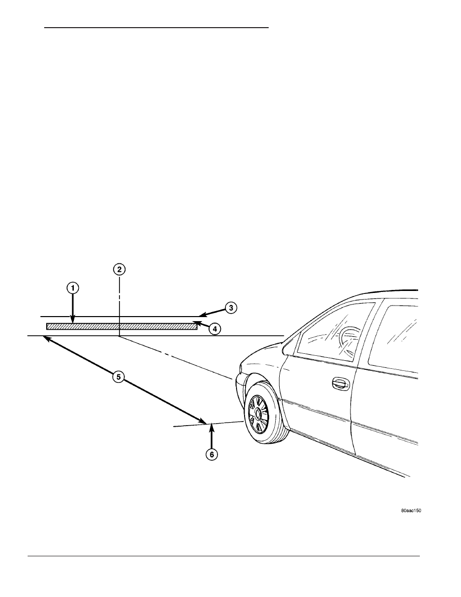
properly aligned fog lamp will project a pattern on
the alignment screen 100 mm (4 in.) below the fog
lamp center line and straight ahead (Fig. 8). To
improve visual interpretation of the fog lamp pattern
on the alignment screen, the headlamps should be in
the “off” position.
The fog lamps are adjusted by a adjustment screw
at the top of the lamp.
STANDARD PROCEDURE - FRONT FOG LAMP
UNIT ALIGNMENT - EXPORT
Prepare an alignment screen (Refer to 8 - ELEC-
TRICAL/LAMPS/LIGHTING
-
EXTERIOR/HEAD-
LAMP
UNIT
-
STANDARD
PROCEDURE).
A
properly aligned fog lamp will project a pattern on
the alignment screen 200 mm (8 in.) below the fog
lamp center line and straight ahead (Fig. 9). To
improve visual interpretation of the fog lamp pattern
on the alignment screen, the headlamps should be in
the “off” position.
The fog lamps are adjusted by a adjustment screw
located on the front side of the fog lamp unit.
Fig. 8 FRONT FOG LAMP UNIT ALIGNMENT
1 - HIGH INTENSITY AREA
4 - 100MM (4 IN.)
2 - CENTER OF VEHICLE
5 - 7.62 METERS (25 FT.)
3 - HORIZONTAL CENTER OF FOG LAMP
6 - FRONT OF FOG LAMP
RS
LAMPS/LIGHTING - EXTERIOR
8L - 9