Chrysler RG Voyager. Manual - part 718
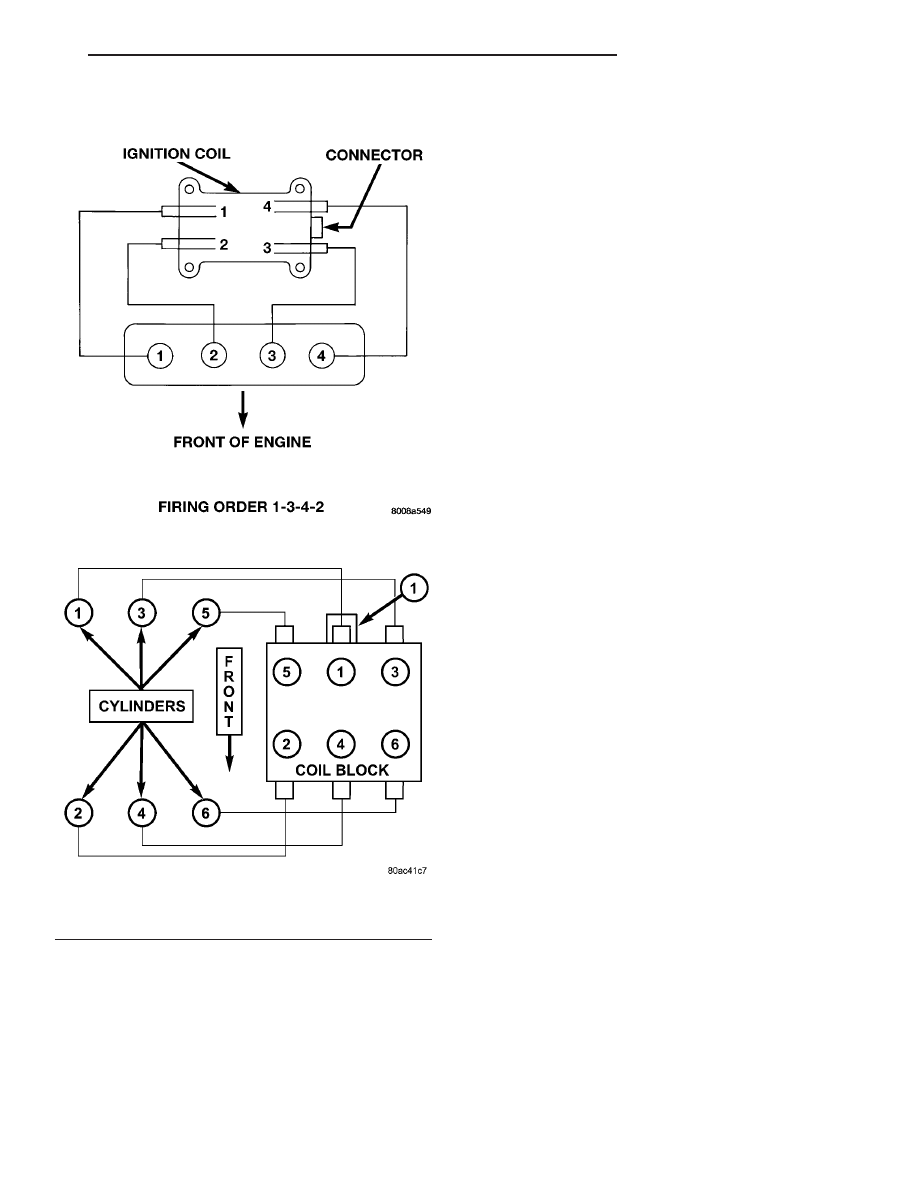
FIRING ORDER
AUTO SHUT DOWN RELAY
DESCRIPTION
The relay is located in the Power Distribution Cen-
ter (PDC). For the location of the relay within the
PDC, refer to the PDC cover for location. Check elec-
trical terminals for corrosion and repair as necessary
OPERATION
The
engine
switched
battery
(NGC
vehicles)
informs the PCM when the ASD relay energizes. A 12
volt signal at this input indicates to the PCM that
the ASD has been activated. This input is also used
to power certain drivers on NGC vehicles.
When energized, the ASD relay on NGC vehicles
provides power to operate the injectors, ignition coil,
generator field, O2 sensor heaters (both upstream
and downstream), evaporative purge solenoid, EGR
solenoid
(if
equipped)
wastegate
solenoid
(if
equipped), and NVLD solenoid (if equipped).
The ASD relay also provides a sense circuit to the
PCM for diagnostic purposes. If the PCM does not
receive 12 volts from this input after grounding the
control side of the ASD relay, it sets a Diagnostic
Trouble Code (DTC). The PCM energizes the ASD
any time there is an engine speed that exceeds a pre-
determined value (typically about 50 rpm). The ASD
relay can also be energized after the engine has been
turned off to perform an O2 sensor heater test, if
vehicle is equipped with OBD II diagnostics.
As mentioned earlier, the PCM energizes the ASD
relay during an O2 sensor heater test. On NGC vehi-
cles it checks the O2 heater upon vehicle start. The
PCM still operates internally to perform several
checks, including monitoring the O2 sensor heaters.
FIRING ORDER 2.4L
Firing Order 1-2-3-4-5-6 3.3/3.8L
1 - Electrical Connector
RS
IGNITION CONTROL
8I - 3
IGNITION CONTROL (Continued)