Chrysler RG Voyager. Manual - part 666


  Index      Chrysler     Chrysler RG Voyager - service repair manual 2005 year


Search            


Content   ..  664  665  666  667   ..


Chrysler RG Voyager. Manual - part 666


(9) Remove the disc brake caliper to adapter guide

pin bolts (Fig. 132).

(10) Remove rear caliper from adapter using the

following procedure. First rotate front of caliper up
from the adapter. Then pull the rear of the caliper
and the outboard brake shoe anti-rattle clip out from
under the rear abutment on the adapter (Fig. 133).

(11) Support caliper to prevent the weight of the

caliper from damaging the flexible brake hose (Fig.
134).

(12) Remove the rotor from the hub/bearing.
(13) Remove the park brake cable mounting bolt to

adapter.

(14) Remove the end of the park brake cable from

the actuator lever on the adapter (Fig. 135).

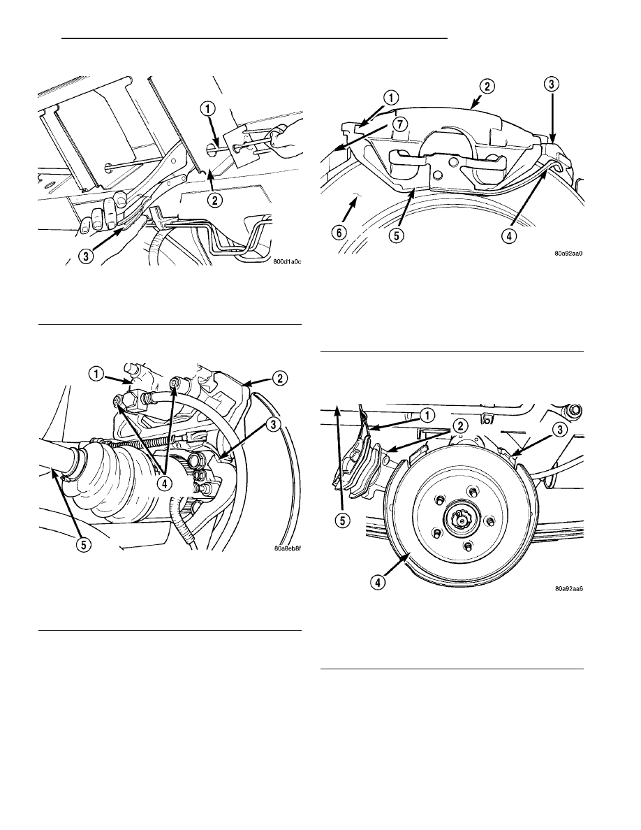
Fig. 131 Locking Out Automatic Adjuster

1 - PARK BRAKE CABLE
2 - REAR BODY OUTRIGGER BRACKET
3 - LOCKING PLIERS

Fig. 132 Removing Caliper Guide Pin Bolts

1 - DISC BRAKE CALIPER
2 - ADAPTER
3 - AXLE
4 - GUIDE PIN BOLTS
5 - DRIVESHAFT (AWD MODELS ONLY)

Fig. 133 Removing/Installing Caliper

1 - LIFT THIS END OF CALIPER AWAY FROM ADAPTER FIRST
2 - DISC BRAKE CALIPER
3 - ADAPTER ABUTMENT
4 - OUTBOARD BRAKE SHOE HOLD DOWN CLIP
5 - OUTBOARD BRAKE SHOE
6 - ROTOR
7 - ADAPTER

Fig. 134 Correctly Supported Caliper

1 - WIRE
2 - CALIPER
3 - ADAPTER
4 - ROTOR
5 - INNER FENDER

RS

BRAKES - BASE

5 - 77

SHOES - PARKING BRAKE (Continued)

(15) Remove the end of the park brake cable from

the adapter. Park brake cable is removed from
adapter using a 1/2 wrench slipped over the park
brake cable retainer as show in (Fig. 136) to com-
press the locking tabs on the park brake cable
retainer.

(16) AWD only - Remove ABS wheel speed sensor

head from hub/bearing (Fig. 137).

(17) FWD only - Remove the ABS wheel speed sen-

sor from the hub/bearing in the following fashion:

(a) Remove secondary (yellow) retaining clip at

rear of wheel speed sensor head (Fig. 138).

(b) Push up on metal retaining clip (Fig. 138)

until it bottoms. This will release wheel speed sen-
sor head from hub and bearing. While holding
metal clip up, pull back on wheel speed sensor
head removing it from hub and bearing.

(c) Remove wheel speed sensor from hub/bear-

ing.

(18) Remove

the

hub/bearing-to-axle

mounting

bolts (Fig. 139).

Fig. 135 Park Brake Cable Attachment To Actuator

1 - ADAPTER
2 - PARK BRAKE CABLE
3 - ACTUATOR
4 - AXLE
5 - DRIVESHAFT
6 - PARK BRAKE CABLE RETAINER
7 - HORSESHOE CLIP

Fig. 136 Park Brake Cable Removal From Adapter

1 - DRIVESHAFT
2 - 1/2” WRENCH
3 - PARK BRAKE CABLE
4 - PARK BRAKE CABLE RETAINER
5 - ADAPTER

Fig. 137 Speed Sensor Attaching Bolt (AWD)

1 - ADAPTER
2 - TONE WHEEL
3 - WHEEL SPEED SENSOR
4 - AXLE
5 - BOLT
6 - DRIVESHAFT

Fig. 138 Sensor Connection At Hub And Bearing

1 - SECONDARY SENSOR RETAINING CLIP
2 - METAL SENSOR RETAINING CLIP
3 - HUB AND BEARING

5 - 78

BRAKES - BASE

RS

SHOES - PARKING BRAKE (Continued)

(19) Remove the hub/bearing (Fig. 140).

CAUTION: Corrosion may occur between the hub/
bearing and the axle flange. If this occurs, the hub/
bearing will be difficult to remove from the axle and
disc brake caliper adapter. If the hub/bearing will
not come out by pulling on it by hand, don’t not
pound on it with a hammer. Pounding on the hub/
bearing will damage it. To remove a hub/bearing
that is corroded in place, lightly tap the disc brake
caliper adapter using a soft-face hammer. This will
remove both the caliper adapter and hub/bearing

together from the axle. With a helper supporting the
caliper adapter in his hands, position Remover,
Special Tool 8214-1, on the cast housing of hub/
bearing (Fig. 141). Do not position the special tool
on the inner race of hub/bearing. Lightly strike the
Remover with a hammer to remove the hub/bearing
from the caliper adapter.

(20) Remove the adapter from the rear axle.
(21) Mount the adapter in a vise using the anchor

boss for the park brake cable (Fig. 142).

(22) Remove the lower return spring (Fig. 143)

from the leading and trailing park brake shoes.

Fig. 139 Hub/Bearing Mounting Bolts (AWD Shown)

1 - DRIVESHAFT
2 - MOUNTING BOLTS
3 - AXLE
4 - MOUNTING BOLTS
5 - ADAPTER

Fig. 140 Hub/Bearing Removal/Installation (AWD

Shown)

1 - PARK BRAKE BRAKE SHOE
2 - OUTER C/V JOINT
3 - HUB/BEARING
4 - PARK BRAKE BRAKE SHOE
5 - STUB SHAFT

Fig. 141 Hub/Bearing Removal From Caliper Adapter

1 - SPECIAL TOOL 8214-1
2 - PARK BRAKE CABLE
3 - DISC BRAKE CALIPER ADAPTER
4 - HUB/BEARING

Fig. 142 Adapter Mounted In Vise

1 - ADAPTER
2 - PARK BRAKE CABLE BOSS
3 - VISE
4 - PARK BRAKE BRAKE SHOES

RS

BRAKES - BASE

5 - 79

SHOES - PARKING BRAKE (Continued)

(23) Remove the hold down spring and pin (Fig.

144) from the leading park brake shoe.

(24) Remove the adjuster (Fig. 145) from the lead-

ing and trailing park brake shoe.

(25) Remove the leading park brake shoe (Fig.

146) from the adapter. Leading brake shoe is
removed by rotating the bottom of the brake shoe
inward (Fig. 146) until the top of the brake shoe can
be removed from the brake shoe anchor. Then remove
the upper return springs (Fig. 146) from the leading
brake shoe.

(26) Remove the upper return springs (Fig. 147)

from the trailing park brake shoe.

Fig. 143 Lower Return Spring

1 - ADAPTER
2 - LEADING PARK BRAKE SHOE
3 - RETURN SPRING
4 - TRAILING PARK BRAKE SHOE

Fig. 144 Leading Brake Shoe Hold Down Pin And

Spring

1 - ADAPTER
2 - LEADING PARK BRAKE SHOE
3 - ALLEN WRENCH
4 - HOLD DOWN SPRING/PIN

Fig. 145 Brake Shoe Adjuster

1 - LEADING PARK BRAKE SHOE
2 - ADJUSTER
3 - TRAILING PARK BRAKE SHOE

Fig. 146 Primary Brake Shoe Remove/Install

1 - PARK BRAKE ACTUATOR
2 - ANCHOR
3 - LEADING PARK BRAKE SHOE
4 - UPPER RETURN SPRINGS
5 - TRAILING PARK BRAKE SHOE

5 - 80

BRAKES - BASE

RS

SHOES - PARKING BRAKE (Continued)


Content   ..  664  665  666  667   ..