Chrysler RG Voyager. Manual - part 525


  Index      Chrysler     Chrysler RG Voyager - service repair manual 2005 year


Search            


Content   ..  523  524  525  526   ..


Chrysler RG Voyager. Manual - part 525


ASSEMBLY

(1) Position synchronizer hub onto work bench.

Hub is non-directional.

(2) Install springs into hub slot.
(3) Insert key into hub and spring.
(4) Apply petroleum jelly to the hole in the key.

Insert balls into each key.

(5) Slide sleeve over the hub and depress balls as

you carefully slip the sleeve into position.

VEHICLE SPEED SENSOR

REMOVAL

(1) Raise vehicle on hoist.
(2) Disconnect the speed sensor connector (Fig.

299).

CAUTION: Clean area around speed sensor before
removing to prevent dirt from entering the transaxle
during speed sensor removal.

(3) Remove speed sensor retaining bolt (Fig. 299).

(4) Remove speed sensor from transaxle.

CAUTION: Carefully remove vehicle speed sensor
so that sensor drive gear does not fall into trans-
axle. Should sensor drive gear fall into the trans-
axle during sensor removal, drive gear must be
reattached to sensor.

(5) Remove speed sensor drive gear from speed

sensor.

INSTALLATION

(1) Install pinion gear to speed sensor (Fig. 299).
(2) Using a NEW o-ring, install the speed sensor

to the transaxle (Fig. 299).

(3) Install the bolt and torque to 7 N·m (60 in.

lbs.).

(4) Connect speed sensor connector (Fig. 299).
(5) Lower vehicle and road test to verify proper

speedometer operation.

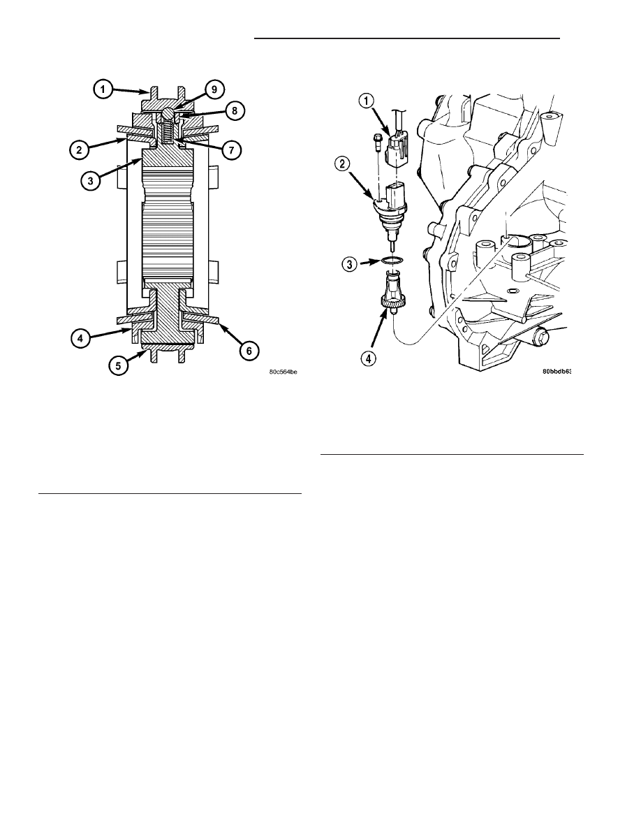
Fig. 298 1/2 Synchronizer Assembly

1 - SLEEVE
2 - REACTOR RING (2)
3 - HUB
4 - BLOCKER RING (2)
5 - SLEEVE
6 - FRICTION CONE (2)
7 - SPRING (3)
8 - KEY (3)
9 - BALL (3)

Fig. 299 Speed Sensor and Pinion Removal/

Installation—Typical

1 - CONNECTOR
2 - SENSOR
3 - O-RING
4 - GEAR

21a - 122

T850 MANUAL TRANSAXLE

RG

SYNCHRONIZER (Continued)

EMISSIONS CONTROL

TABLE OF CONTENTS

page

page

EMISSIONS CONTROL 2.5L/2.8L TURBO

DIESEL
DESCRIPTION

. . . . . . . . . . . . . . . . . . . . . . . . . . 1

SPECIFICATIONS - TORQUE

. . . . . . . . . . . . . . . 2

EXHAUST GAS RECIRCULATION

. . . . . . . . . . . . 3

ON-BOARD DIAGNOSTICS

. . . . . . . . . . . . . . . . . 5

EMISSIONS CONTROL
2.5L/2.8L TURBO DIESEL

DESCRIPTION

The 2.5L/2.8L diesel Engine Control Module (ECM)

controls many different circuits in the fuel injection
pump and engine systems. If the ECM senses a prob-
lem with a monitored circuit that indicates an actual
problem, a Diagnostic Trouble Code (DTC) will be
stored in the ECM’s memory, and eventually may
illuminate the MIL (Malfunction Indicator Lamp)
constantly while the key is on. If the problem is
repaired, or is intermittent, the ECM will erase the
DTC after 40 warm-up cycles without the fault
detected. A warm-up cycle consists of starting the
vehicle when the engine is cold, then the engine is
warmed up to a certain temperature, and finally, the
engine temperature falls to ambient temperature,
when the key is turned off.

Certain criteria must be met for a DTC to be

entered into ECM memory. The criteria may be a
specific range of engine rpm, engine or fuel tempera-
ture and/or input voltage to the ECM. A DTC indi-
cates that the ECM has identified an abnormal
signal in a circuit or the system.

There are several operating conditions that the

ECM does not monitor and set a DTC for. Refer to
the following Monitored Circuits and Non–Monitored
Circuits in this section.

ECM MONITORED SYSTEMS

The ECM can detect certain problems in the elec-

trical system.

Open or Shorted Circuit – The ECM will not

distinguish between an open or a short to ground,
however the ECM can determine if there is excessive
current on a circuit, such as a short to voltage or a
decrease in component resistance.

Output Device Current Flow – The ECM senses

whether the output devices are electrically connected.

If there is a problem with the circuit, the ECM

senses whether the circuit is open, shorted to ground
(–), or shorted to (+) voltage.

Fuel Pressure: High fuel pressure is controlled by

the fuel injection pump, fuel pressure solenoid, and
fuel pressure sensor. The ECM uses inputs from the
sensor and solenoid to calculate and determine if a
high fuel pressure problem exists.

Fuel Injector Malfunctions: The ECM can deter-

mine if a fuel injector has an electrical problem. The
fuel injectors on the diesel engine are controlled by
the ECM.

ECM NON–MONITORED SYSTEMS

The ECM does not monitor the following circuits,

systems or conditions that could have malfunctions
that result in driveability problems. A DTC will not
be displayed for these conditions.

Cylinder Compression: The ECM cannot detect

uneven, low, or high engine cylinder compression.

Exhaust System: The ECM cannot detect a

plugged, restricted or leaking exhaust system.

Vacuum Assist: Leaks or restrictions in the vac-

uum circuits of the Exhaust Gas Recirculation Sys-
tem (EGR) are not monitored by the ECM.

ECM System Ground: The ECM cannot deter-

mine a poor system ground. However, a DTC may be
generated as a result of this condition.

ECM/PCM Connector Engagement: The ECM

cannot determine spread or damaged connector pins.
However, a DTC may be generated as a result of this
condition.

HIGH AND LOW LIMITS

The ECM compares input signals from each input

device. There are high and low limits that are pro-
grammed into the ECM for that device. If the inputs
are not within specifications and other DTC criteria
are met, a DTC will be stored in memory. Other DTC
criteria might include engine rpm limits or input
voltages from other sensors or switches. The other
inputs might have to be sensed by the ECM when it
senses a high or low input voltage from the control
system device in question.

RG

EMISSIONS CONTROL

25a - 1

SPECIFICATIONS - TORQUE

2.5L / 2.8L DIESEL - TORQUE SPECIFICATIONS

DESCRIPTION

N·m

Ft. Lbs.

In. Lbs.

EGR Pipe to EGR Bolts

32.4

24

EGR Pipe to Exhaust

Manifold

27.5

21

EGR Valve Nuts

32.4

24

25a - 2

EMISSIONS CONTROL

RG

EMISSIONS CONTROL 2.5L/2.8L TURBO DIESEL (Continued)

EXHAUST GAS RECIRCULATION

TABLE OF CONTENTS

page

page

EXHAUST GAS RECIRCULATION

DESCRIPTION

. . . . . . . . . . . . . . . . . . . . . . . . . . 3

OPERATION

. . . . . . . . . . . . . . . . . . . . . . . . . . . . 3

VALVE

DESCRIPTION

. . . . . . . . . . . . . . . . . . . . . . . . . . 3

OPERATION

. . . . . . . . . . . . . . . . . . . . . . . . . . . . 3

REMOVAL

. . . . . . . . . . . . . . . . . . . . . . . . . . . . . 4

INSTALLATION

. . . . . . . . . . . . . . . . . . . . . . . . . . 4

EXHAUST GAS
RECIRCULATION

DESCRIPTION

The EGR system reduces oxides of nitrogen (NOx)

in the engine exhaust. This is accomplished by allow-
ing a predetermined amount of hot exhaust gas to
recirculate and dilute the incoming charge air.

A malfunctioning EGR system can cause engine

stumble, sags, or hesitation, rough idle, engine stall-
ing and poor driveability.

OPERATION

The system consists of:
• An EGR valve assembly. The valve is located on

the rear of the engine above the exhaust manifold.

• An EGR solenoid. The EGR solenoid controls the

“on time” of the EGR valve.

• The ECM operates the EGR solenoid. The ECM

is located in the left front corner of the engine com-
partment, in front of the battery.

• An EGR tube connects a passage in the EGR

valve to the intake manifold.

• The vacuum pump supplies vacuum for the EGR

solenoid and the EGR valve. This pump also supplies
vacuum for operation of the power brake booster and
the heating and air conditioning system. The pump is
located internally in the front of the engine block and
is driven by the crankshaft gear.

• Vacuum lines and hoses connect the various

components.

When the ECM supplies a variable ground signal

to the EGR solenoid, EGR system operation starts to
occur. The ECM will monitor and determine when to
supply and remove this variable ground signal. This
will depend on inputs from the engine coolant tem-
perature, throttle position and engine speed sensors.

When the variable ground signal is supplied to the

EGR solenoid, vacuum from the vacuum pump will

be allowed to pass through the EGR solenoid and on
to the EGR valve with a connecting hose.

Exhaust gas recirculation will begin in this order

when:

• The ECM determines that EGR system opera-

tion is necessary.

• The engine is running to operate the vacuum

pump.

• A variable ground signal is supplied to the EGR

solenoid.

• Variable vacuum passes through the EGR sole-

noid to the EGR valve.

• The inlet seat (poppet valve) at the bottom of

the EGR valve opens to recirculate exhaust gas back
into the intake manifold.

The EGR system will be shut down by the ECM

after 60 seconds of continuous engine idling to
improve idle quality.

VALVE

DESCRIPTION

The EGR system consists of (Fig. 1):
• EGR valve

• EGR tube

• Vacuum hoses

• EGR solenoid

OPERATION

The EGR system reduces oxides of nitrogen (NOx)

in engine exhaust. Formation of NOx increases pro-
portionally with combustion temperature. To reduce
the emission of these oxides, the cylinder tempera-
ture must be lowered. The system allows a predeter-
mined amount of hot exhaust gas to recirculate and
dilute the incoming charge air. The diluted air mix-
ture reduces peak flame temperature during combus-
tion.

RG

EXHAUST GAS RECIRCULATION

25a - 3


Content   ..  523  524  525  526   ..