Chrysler RG Voyager. Manual - part 512


  Index      Chrysler     Chrysler RG Voyager - service repair manual 2005 year


Search            


Content   ..  510  511  512  513   ..


Chrysler RG Voyager. Manual - part 512


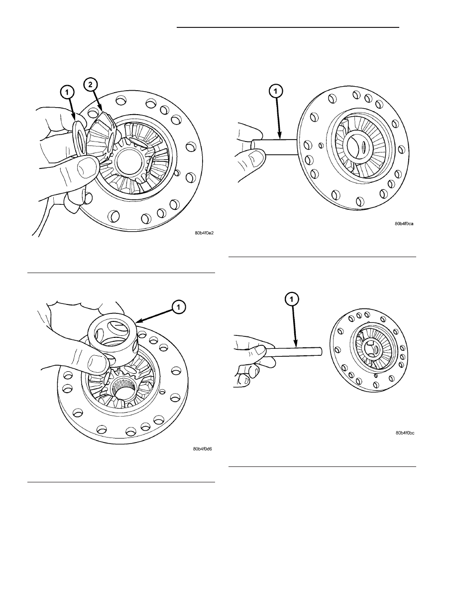
(3) Install four (4) pinion gears and thrust washers

(Fig. 123).

(4) Install pinion shaft retaining ring (Fig. 124).

(5) Install two (2) short pinion shafts (Fig. 125).

(6) Install one (1) long pinion shaft (Fig. 126).

Fig. 123 Pinion Gear and Thrust Washer

1 - THRUST WASHER (4)
2 - PINION GEAR (4)

Fig. 124 Pinion Shaft Retaining Ring

1 - RETAINING RING

Fig. 125 Short Pinion Shaft (2)

1 - PINION SHAFT (SHORT (2))

Fig. 126 Long Pinion Shaft

1 - PINION SHAFT (LONG)

21a - 70

T850 MANUAL TRANSAXLE

RG

DIFFERENTIAL (Continued)

(7) Install differential side gear.
(8) Install side gear thrust washer (Fig. 127).

(9) Install differential support plate. Align support

plate to differential case with alignment pins 8470
(Fig. 128).

(10) Install thrust buttons 8491 to both bearing

journals and press halves together using an arbor
press (Fig. 129).

Fig. 127 Side Gear Thrust Washer

1 - SIDE GEAR THRUST WASHER
2 - DIFFERENTIAL SIDE GEAR

Fig. 128 Align Differential Support to Case

1 - ALIGNMENT PIN 8470
2 - DIFFERENTIAL SUPPORT PLATE
3 - DIFFERENTIAL CASE

Fig. 129 Installing Differential Support

1 - ARBOR PRESS
2 - BUTTON 8491
3 - DIFFERENTIAL SUPPORT PLATE
4 - ALIGNMENT PIN 8470
5 - DIFFERENTIAL CASE

RG

T850 MANUAL TRANSAXLE

21a - 71

DIFFERENTIAL (Continued)

(11) Install ring gear into position, start three ring

gear-to-differential case bolts by hand (120° apart),
and install alignment pins 8470 (Fig. 130).

(12) Torque three ring gear bolts to draw ring gear

into position. Remove alignment pins, install remain-
ing ring gear-to-differential case bolts and torque to
95 N·m (70 ft. lbs.) (Fig. 131).

(13) Install tapered roller bearings using installer

8473 and an arbor press (Fig. 132). Insert button
8491 on opposite journal to protect journal and/or
bearing during press operation. Repeat the same
operation on opposite side.

(14) Measure and verify differential side gear end

play. (Refer to 21 - TRANSMISSION/TRANSAXLE/
MANUAL/DIFFERENTIAL - ADJUSTMENTS).

Fig. 130 Ring Gear Alignment/Installation

1 - ALIGNMENT PIN 8470
2 - BOLT

Fig. 131 Ring Gear-to-Differential Case Bolts

1 - BOLT (12)
2 - DIFFERENTIAL SUPPORT
3 - RING GEAR

Fig. 132 Differential Side Bearing Installation

1 - ARBOR PRESS
2 - INSTALLER 8473
3 - BEARING
4 - BUTTON 8491

21a - 72

T850 MANUAL TRANSAXLE

RG

DIFFERENTIAL (Continued)

ADJUSTMENTS

ADJUSTMENT - DIFFERENTIAL TURNING
TORQUE

NOTE: Differential turning torque should only be
measured with the geartrain out of the transaxle. If
measurement is taken with transaxle assembled, an
inaccurate measurement will result.

NOTE: All differential cover-to-case bolts and exten-
sion housing-to-case bolts must be installed and
torqued to obtain accurate measurement.

(1) If transaxle is assembled, remove geartrain

and leave differential in place. (Refer to 21 - TRANS-
MISSION/TRANSAXLE/MANUAL - DISASSEMBLY)

(2) Install differential cover and torque differential

cover-to-case bolts to 54 N·m (40 ft. lbs.).

(3) Install extension housing and torque extension

housing-to-case bolts to 28 N·m (250 in. lbs.).

(4) Place transaxle on work bench so axle center-

line is parallel to the ground.

(5) Install turning torque tool C-4995 to differen-

tial at side opposite extension housing.

(6) Using an in. lb./N·m dial indicator, rotate dif-

ferential case multiple times and record measure-
ment (Fig. 133). Differential turning torque should be
within 2.3-3.4 N·m (20-30 in. lbs.). Refer to shim

chart for proper shim selection. If turning torque
measured is less than 2.3 N·m (20 in. lbs.), install a
thicker shim. If turning torque measured is greater
than 3.4 N·m (30 in. lbs.), install a thinner shim.

Fig. 133 Differential Turning Torque Measurement

1 - DIAL TORQUE WRENCH
2 - TOOL C-4995

RG

T850 MANUAL TRANSAXLE

21a - 73

DIFFERENTIAL (Continued)


Content   ..  510  511  512  513   ..