Chrysler RG Voyager. Manual - part 510


  Index      Chrysler     Chrysler RG Voyager - service repair manual 2005 year


Search            


Content   ..  508  509  510  511   ..


Chrysler RG Voyager. Manual - part 510


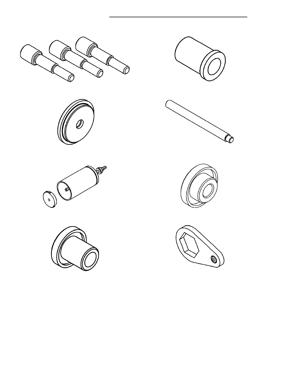
Alignment Pins, 8470

Installer, 8471

Race Remover, 8472

Bearing Installer, 8473

Remover/Installer, 8474

Installer, 8475

Installer, 8476

Wrench, 8478

21a - 62

T850 MANUAL TRANSAXLE

RG

T850 MANUAL TRANSAXLE (Continued)

Stake Tool, 8479

Installer, 8481

Bearing Installer, 8482

Fixture, 8483

Fixture, 8487

Lifting Bar, 8489

Thrust Buttons, 8491

Wrench, 8827

RG

T850 MANUAL TRANSAXLE

21a - 63

T850 MANUAL TRANSAXLE (Continued)

AXLE SEALS

REMOVAL

(1) Raise vehicle on hoist.
(2) Remove one or both front halfshaft assemblies.

(Refer to 3 - DIFFERENTIAL & DRIVELINE/HALF
SHAFT - REMOVAL)

(3) Using a suitable screwdriver, remove one or

both axle seals (Fig. 102).

INSTALLATION

(1) Using driver handle C-4171 and installer 8476,

install axle seals into position (Fig. 103) (Fig. 104).

(2) Install one or both front halfshaft assemblies.

(Refer to 3 - DIFFERENTIAL & DRIVELINE/HALF
SHAFT - INSTALLATION)

(3) Check transaxle fluid level and adjust if neces-

sary. (Refer to 21 - TRANSMISSION/TRANSAXLE/
MANUAL/FLUID - STANDARD PROCEDURE)

(4) Lower vehicle.

Fig. 102 Axle Seal Removal (Extension Housing

Side Shown)

1 - SCREWDRIVER
2 - AXLE SEAL
3 - EXTENSION HOUSING

Fig. 103 Axle Seal Installation

1 - SEAL
2 - INSTALLER 8476
3 - DRIVER HANDLE C-4171

Fig. 104 Axle Seal Installation (Extension Housing

Side)

1 - EXTENSION HOUSING
2 - SEAL
3 - INSTALLER 8476
4 - DRIVER HANDLE C-4171

21a - 64

T850 MANUAL TRANSAXLE

RG

BACK-UP LAMP SWITCH

REMOVAL

(1) Raise vehicle on hoist.
(2) Disconnect back-up lamp switch connector.
(3) Remove back-up lamp switch (Fig. 105).

INSTALLATION

(1) Install back-up lamp switch (Fig. 105) and

torque to 23 N·m (17 ft. lbs.) using Tool 8827.

(2) Connect back-up lamp switch connector.
(3) Lower vehicle.

DIFFERENTIAL

DESCRIPTION

The T850 differential is a conventional open

design. It consists of a ring gear and a two-piece dif-
ferential case. The differential case contains the pin-
ion and side gears, three floating pinion shafts, and a
pinion shaft retaining ring (Fig. 106). The differential
case is supported in the transaxle by tapered roller
bearings.

OPERATION

The differential assembly is driven by the interme-

diate shaft via the ring gear. The ring gear drives the
differential case, and the case drives the halfshafts
through the differential gears. The differential pinion
and side gears are supported in the case by pinion
shafts and thrust washers. Differential pinion and
side gears make it possible for front wheels to rotate
at different speeds while cornering.

Fig. 105 Back-Up Lamp Switch

1 - BACK-UP LAMP SWITCH

Fig. 106 Differential Assembly

1 - RING GEAR
2 - SUPPORT PLATE
3 - SIDE GEAR (2)
4 - PINION GEAR (4)
5 - BOLT (12)
6 - PINION SHAFT (2-SHORT)
7 - PINION SHAFT (1-LONG)
8 - THRUST WASHER (2)
9 - RETAINING RING
10 - DIFFERENTIAL CASE

RG

T850 MANUAL TRANSAXLE

21a - 65


Content   ..  508  509  510  511   ..