Chrysler RG Voyager. Manual - part 500


  Index      Chrysler     Chrysler RG Voyager - service repair manual 2005 year


Search            


Content   ..  498  499  500  501   ..


Chrysler RG Voyager. Manual - part 500


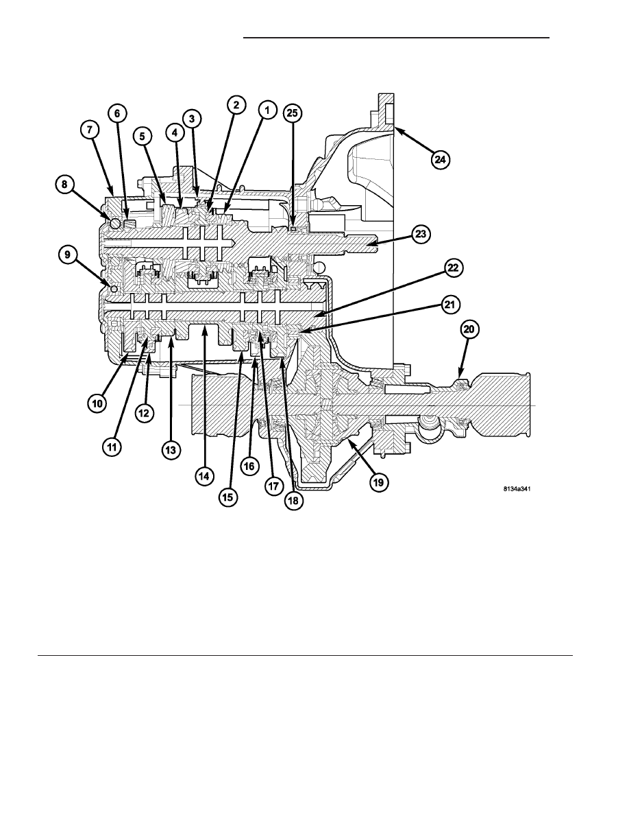
Fig. 1 NV T850 Transaxle

1 - 3RD GEAR (SPEED)

9 - INTERMEDIATE SHAFT BEARING
(SEALED BALL)

17 - 1/2 SYNCHRONIZER

2 - 3/4 SYNCHRONIZER

10 - REVERSE GEAR

18 - 1ST GEAR (SPEED)

3 - 3/4 SHIFT FORK

11 - 5/R SYNCHRONIZER

19 - DIFFERENTIAL ASSEMBLY

4 - 4TH GEAR (SPEED)

12 - 5/R SHIFT FORK

20 - EXTENSION HOUSING

5 - 5TH GEAR (INPUT)

13 - 5TH GEAR (SPEED)

21 - INTERMEDIATE SHAFT BEARING
(CAGED ROLLER)

6 - REVERSE IDLER GEAR

14 - 3/4 CLUSTER GEAR

22 - INTERMEDIATE SHAFT

7 - END COVER, REAR

15 - 2ND GEAR (SPEED)

23 - INPUT SHAFT

8 - INPUT SHAFT BEARING (SEALED
BALL)

16 - 1/2 SHIFT FORK

24 - CASE

25 - INPUT SHAFT BEARING (ROLLER)

21a - 22

T850 MANUAL TRANSAXLE

RG

T850 MANUAL TRANSAXLE (Continued)

The NV T850 transaxle is available with the 2.4L

Gas and 2.5L Turbo Diesel engine options. Unique
gearing tailored to the performance characteristics of
each engine provides optimum driveability, gradabil-
ity, and acceleration. The gear ratios are as follows:

GEAR

RATIO

1st

3.65

2nd

2.05

3rd

1.37

4th

0.97

5th

0.76

Reverse

3.47

Final Drive Ratio

3.77

Overall Top Gear

2.85

TRANSAXLE IDENTIFICATION

NOTE: Since transaxles use unique gear ratios for
each of the two engine applications, it is imperative
that the transaxle is properly identified, and the cor-
rect transaxle assembly number is used when
ordering service parts.

The transaxle model, assembly part number, build

date, and final drive ratio (FDR) can be found on a
metal tag fastened to the transaxle case on the bell-
housing (Fig. 2). A barcode label is also glued to the
transaxle bellhousing, and it too includes the trans-
axle part number.

Fig. 2 T850 Transaxle Identification

1 - TRANSAXLE BELLHOUSING
2 - BARCODE LABEL
3 - I.D. TAG

RG

T850 MANUAL TRANSAXLE

21a - 23

T850 MANUAL TRANSAXLE (Continued)

OPERATION

NEUTRAL

Engine power is transmitted to the tinput shaft.

Engine power is transmitted to the input shaft via
the clutch assembly and the input shaft turns. Since
no synchronizers are engaged on either the input or
intermediate shafts, power is not transmitted to the
intermediate shaft and the differential does not turn
(Fig. 3).

Fig. 3 Neutral Gear Operation

21a - 24

T850 MANUAL TRANSAXLE

RG

T850 MANUAL TRANSAXLE (Continued)

1ST GEAR

Engine power is transmitted to the input shaft via

the clutch assembly and the input shaft turns. The
input shaft first gear is integral to the input shaft,
and is in constant mesh with the intermediate shaft
first speed gear. Because of this constant mesh, the
intermediate shaft first speed gear freewheels until
first gear is selected. As the gearshift lever is moved
to the first gear position, the 1-2 fork moves the 1-2
synchronizer sleeve towards first gear on the inter-
mediate shaft. The synchronizer sleeve engages the
first gear clutch teeth, fixing the gear to the interme-
diate shaft, and allowing power to transmit through
the intermediate shaft to the differential (Fig. 4).

Fig. 4 1st Gear Operation

RG

T850 MANUAL TRANSAXLE

21a - 25

T850 MANUAL TRANSAXLE (Continued)


Content   ..  498  499  500  501   ..