Chrysler RG Voyager. Manual - part 499


  Index      Chrysler     Chrysler RG Voyager - service repair manual 2005 year


Search            


Content   ..  497  498  499  500   ..


Chrysler RG Voyager. Manual - part 499


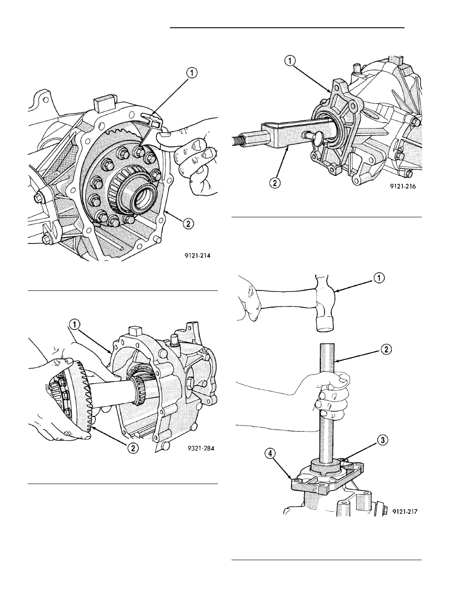
(3) Remove ring gear oil trough (Fig. 44).

(4) Remove input shaft and ring gear from case

(Fig. 45).

(5) Use Special Tool No. 7794-A (seal puller) to

remove seal (Fig. 46).

INSTALLATION

The Power Transfer Unit must be removed from

the vehicle to service this seal. Refer to Power Trans-
fer Unit Removal in this section for procedures.

(1) Clean and inspect seal area.

(2) Lay housing on bench and install new seal with

seal driver C-4657 and handle C-4171 (Fig. 47). The
seal must be installed with the spring side facing
towards the ring gear. Drive the seal in until it bot-
toms against the case shoulder.

Fig. 44 Oil Trough

1 - OIL TROUGH
2 - POWER TRANSFER UNIT

Fig. 45 Input Shaft and Ring Gear Removal

1 - POWER TRANSFER UNIT
2 - RING GEAR

Fig. 46 Seal Removal

1 - POWER TRANSFER UNIT
2 - SPECIAL TOOL 7794–A

Fig. 47 Seal Installation

1 - HAMMER
2 - SPECIAL TOOL C-4171
3 - SPECIAL TOOL C-4657
4 - POWER TRANSFER UNIT

21a - 18

POWER TRANSFER UNIT

RG

INPUT SHAFT SEAL (Continued)

(3) Install input shaft.
(4) Install oil trough.
(5) Apply Mopar

t Gasket Maker or equivalent to

sealing surfaces of end cover and reinstall. Tighten
bolts to 28 N·m (250 in. lbs.)

CAUTION: When end cover is installed be careful
not to damage the P.T.U. Input Shaft Cover Seal.

(6) Reinstall P.T.U. assembly into vehicle.
(7) Check and fill fluids as required.

OUTER HALF SHAFT SEAL

REMOVAL

The outer half shaft seal is located on the outside

of the end cover. The P.T.U. does not have to be
removed to replace this seal.

(1) Lift vehicle on hoist.
(2) Remove right front half shaft from vehicle.
(3) Remove seal with a chisel and hammer (Fig.

48).

INSTALLATION

The outer half shaft seal is located on the outside

of the end cover. The P.T.U. does not have to be
removed to replace this seal.

(1) Clean and inspect seal area.

(2) Install new seal with seal installer MD998334

(Fig. 49).

(3) Reinstall right front half shaft.
(4) Check and fill fluids as required.

REAR COVER O-RING

REMOVAL

(1) Raise vehicle on hoist.
(2) Remove rear cover retaining bolts (Fig. 50).

Fig. 48 Seal Removal

1 - HAMMER
2 - CHISEL
3 - SEAL
4 - POWER TRANSFER UNIT

Fig. 49 Seal Installation

1 - BEARING
2 - SNAP RING PLIERS
3 - BEARING SNAP RING

Fig. 50 Rear Cover Bolts

1 - OUTPUT FLANGE SEAL
2 - REAR COVER
3 - OUTPUT SHAFT

RG

POWER TRANSFER UNIT

21a - 19

INPUT SHAFT SEAL (Continued)

(3) Index rear cover to the case for later reassem-

bly (Fig. 51).

(4) Pull rear cover out of the P.T.U. case (Fig. 52).

(5) Remove rear cover O-Ring (Fig. 53).

INSTALLATION

(1) To install, reverse removal procedure.

Fig. 51 Mark Rear Cover

1 - REAR COVER
2 - OUTPUT SHAFT
3 - PAINT MARK

Fig. 52 Rear Cover Removal

1 - POWER TRANSFER UNIT ASSEMBLY
2 - REAR COVER
3 - O-RING

Fig. 53 O-Ring Removal

1 - REAR COVER
2 - PINION GEAR
3 - O-RING

21a - 20

POWER TRANSFER UNIT

RG

REAR COVER O-RING (Continued)

T850 MANUAL TRANSAXLE

TABLE OF CONTENTS

page

page

T850 MANUAL TRANSAXLE

DESCRIPTION

. . . . . . . . . . . . . . . . . . . . . . . . . 21

OPERATION

. . . . . . . . . . . . . . . . . . . . . . . . . . . 24

DIAGNOSIS AND TESTING - COMMON

PROBLEM CAUSES

. . . . . . . . . . . . . . . . . . . . 31

REMOVAL

. . . . . . . . . . . . . . . . . . . . . . . . . . . . . 31

DISASSEMBLY

. . . . . . . . . . . . . . . . . . . . . . . . . 37

ASSEMBLY

. . . . . . . . . . . . . . . . . . . . . . . . . . . . 45

INSTALLATION

. . . . . . . . . . . . . . . . . . . . . . . . . 54

SPECIFICATIONS - T850 MANUAL

TRANSAXLE

. . . . . . . . . . . . . . . . . . . . . . . . . 59

SPECIAL TOOLS - T850 TRANSAXLE

. . . . . . . . 61

AXLE SEALS

REMOVAL

. . . . . . . . . . . . . . . . . . . . . . . . . . . . . 64

INSTALLATION

. . . . . . . . . . . . . . . . . . . . . . . . . 64

BACK-UP LAMP SWITCH

REMOVAL

. . . . . . . . . . . . . . . . . . . . . . . . . . . . . 65

INSTALLATION

. . . . . . . . . . . . . . . . . . . . . . . . . 65

DIFFERENTIAL

DESCRIPTION

. . . . . . . . . . . . . . . . . . . . . . . . . 65

OPERATION

. . . . . . . . . . . . . . . . . . . . . . . . . . . 65

DISASSEMBLY

. . . . . . . . . . . . . . . . . . . . . . . . . 66

ASSEMBLY

. . . . . . . . . . . . . . . . . . . . . . . . . . . . 69

ADJUSTMENTS

ADJUSTMENT - DIFFERENTIAL TURNING

TORQUE . . . . . . . . . . . . . . . . . . . . . . . . . . . . 73

ADJUSTMENT - DIFFERENTIAL SIDE GEAR

END PLAY . . . . . . . . . . . . . . . . . . . . . . . . . . . 75

FLUID

STANDARD PROCEDURE

STANDARD PROCEDURE - FLUID LEVEL

CHECK . . . . . . . . . . . . . . . . . . . . . . . . . . . . . 75

STANDARD PROCEDURE - FLUID DRAIN

AND FILL . . . . . . . . . . . . . . . . . . . . . . . . . . . . 76

GEARSHIFT BOOT

REMOVAL

. . . . . . . . . . . . . . . . . . . . . . . . . . . . . 76

INSTALLATION

. . . . . . . . . . . . . . . . . . . . . . . . . 77

GEARSHIFT CABLE - CROSSOVER

REMOVAL

. . . . . . . . . . . . . . . . . . . . . . . . . . . . . 77

INSTALLATION

. . . . . . . . . . . . . . . . . . . . . . . . . 80

ADJUSTMENTS

ADJUSTMENT

. . . . . . . . . . . . . . . . . . . . . . . . 83

GEARSHIFT CABLE - SELECTOR

REMOVAL

. . . . . . . . . . . . . . . . . . . . . . . . . . . . . 85

INSTALLATION

. . . . . . . . . . . . . . . . . . . . . . . . . 88

GEARSHIFT KNOB

REMOVAL

. . . . . . . . . . . . . . . . . . . . . . . . . . . . . 91

INSTALLATION

. . . . . . . . . . . . . . . . . . . . . . . . . 91

GEARSHIFT MECHANISM

REMOVAL

. . . . . . . . . . . . . . . . . . . . . . . . . . . . . 92

INSTALLATION

. . . . . . . . . . . . . . . . . . . . . . . . . 94

INPUT SHAFT

DESCRIPTION

. . . . . . . . . . . . . . . . . . . . . . . . . 97

DISASSEMBLY

. . . . . . . . . . . . . . . . . . . . . . . . . 98

ASSEMBLY

. . . . . . . . . . . . . . . . . . . . . . . . . . . 101

INTERMEDIATE SHAFT

DESCRIPTION

. . . . . . . . . . . . . . . . . . . . . . . . 105

DISASSEMBLY

. . . . . . . . . . . . . . . . . . . . . . . . 106

ASSEMBLY

. . . . . . . . . . . . . . . . . . . . . . . . . . . 113

SHIFT COVER

DESCRIPTION

. . . . . . . . . . . . . . . . . . . . . . . . 120

SHIFT FORK AND SHAFT

DESCRIPTION

. . . . . . . . . . . . . . . . . . . . . . . . 121

SYNCHRONIZER

DESCRIPTION

. . . . . . . . . . . . . . . . . . . . . . . . 121

DISASSEMBLY

. . . . . . . . . . . . . . . . . . . . . . . . 121

CLEANING

CLEAN

. . . . . . . . . . . . . . . . . . . . . . . . . . . . 121

INSPECTION

INSPECT

. . . . . . . . . . . . . . . . . . . . . . . . . . . 121

ASSEMBLY

. . . . . . . . . . . . . . . . . . . . . . . . . . . 122

VEHICLE SPEED SENSOR

REMOVAL

. . . . . . . . . . . . . . . . . . . . . . . . . . . . 122

INSTALLATION

. . . . . . . . . . . . . . . . . . . . . . . . 122

T850 MANUAL TRANSAXLE

DESCRIPTION

The NV T850 5-speed transaxle (Fig. 1) is a con-

stant-mesh manual transaxle that is synchronized in
all gear ranges, including reverse.

The transaxle consists of three major sub-assem-

blies: the input shaft, intermediate shaft, and differ-
ential assembly. The transaxle shift system consists
of a mechanical shift cover, rails, forks, and cables.
The unique design of this shift system provides a
higher mechanical advantage, resulting in less fric-
tion and lower shift cable loads for smoother, more
positive operation.

RG

T850 MANUAL TRANSAXLE

21a - 21


Content   ..  497  498  499  500   ..