Chrysler RG Voyager. Manual - part 466


  Index      Chrysler     Chrysler RG Voyager - service repair manual 2005 year


Search            


Content   ..  464  465  466  467   ..


Chrysler RG Voyager. Manual - part 466


Programming Key Failed (Possible Used Key From

Wrong Vehicle) - SKIM is unable to program key due
to one of the following:

• faulty ignition key transponder

• ignition key is programmed to another vehicle.
8 Keys Already Learned, Programming Not Done -

SKIM transponder ID memory is full.

(5) Obtain ignition keys to be programmed from

customer (8 keys maximum).

(6) Using the DRB III

t, erase all ignition keys by

selecting MISCELLANEOUS and ERASE ALL CUR-
RENT IGN. KEYS.

(7) Program all ignition keys.
Learned Key In Ignition - Ignition key transponder

ID is currently programmed in SKIM memory.

REMOVAL

(1) Disconnect negative battery cable.
(2) Remove left front headlamp module (Refer to 8

- ELECTRICAL/LAMPS/LIGHTING - EXTERIOR/
HEADLAMP UNIT - REMOVAL).

(3) Remove lower headlamp assembly mounting

bolt (Fig. 2).

(4) Remove ECM upper mounting bolts (Fig. 3).
(5) Lift ECM from radiator support.
(6) Disconnect ECM electrical connectors.
(7) Separate ECM from mounting bracket.

INSTALLATION

(1) Install ECM on mounting bracket.
(2) Connect ECM electrical connectors.
(3) Place ECM and bracket assembly in position on

radiator support.

(4) Install upper and lower mounting bolts.
(5) Install left headlamp module (Refer to 8 -

ELECTRICAL/LAMPS/LIGHTING

-

EXTERIOR/

HEADLAMP UNIT - INSTALLATION).

(6) Connect negative battery cable.
(7) Program ECM as necessary (Refer to 8 - ELEC-

TRICAL/ELECTRONIC CONTROL MODULES/EN-
GINE

CONTROL

MODULE

-

STANDARD

PROCEDURE).

Fig. 2 ENGINE CONTROL MODULE-LOWER

MOUNTING BOLT

1 - ENGINE CONTROL MODULE (ECM)
2 - INTEGRATED POWER MODULE
3 - ECM LOWER MOUNTING BOLT

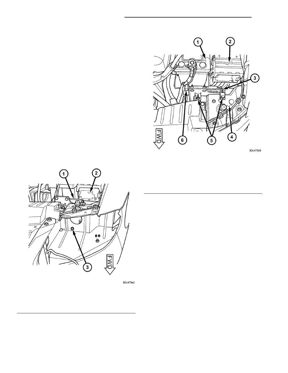
Fig. 3 ENGINE CONTROL MODULE-UPPER

MOUNTING BOLTS

1 - BATTERY
2 - INTEGRATED POWER MODULE
3 - ENGINE CONTROL MODULE
4 - RADIATOR SUPPORT
5 - ECM UPPER MOUNTING BOLTS
6 - ECM ELECTRICAL CONNECTORS

8Ea - 4

ELECTRONIC CONTROL MODULES

RG

ENGINE CONTROL MODULE (Continued)

IGNITION CONTROL

TABLE OF CONTENTS

page

page

GLOW PLUG

DESCRIPTION

. . . . . . . . . . . . . . . . . . . . . . . . . . 1

OPERATION

. . . . . . . . . . . . . . . . . . . . . . . . . . . . 1

GLOW PLUG RELAY

DESCRIPTION

. . . . . . . . . . . . . . . . . . . . . . . . . . 1

OPERATION

. . . . . . . . . . . . . . . . . . . . . . . . . . . . 1

CAMSHAFT POSITION SENSOR

DESCRIPTION

. . . . . . . . . . . . . . . . . . . . . . . . . . 2

OPERATION

. . . . . . . . . . . . . . . . . . . . . . . . . . . . 2

REMOVAL

. . . . . . . . . . . . . . . . . . . . . . . . . . . . . 2

INSTALLATION

. . . . . . . . . . . . . . . . . . . . . . . . . . 3

GLOW PLUG

DESCRIPTION

Glow plugs are used to help start a cold or cool

engine (Fig. 1). The glow plugs will heat up and glow
to heat the combustion chamber of each cylinder. An
individual glow plug is used for each cylinder. Each
glow plug is threaded into the left side of the cylinder
head below the cylinder head cover/intake manifold.

OPERATION

Each glow plug will momentarily draw approxi-

mately 25 amps of electrical current during the ini-
tial key “ON” cycle. This is on a cold or cool engine.
After heating the current draw will drop to approxi-
mately 9–12 amps per plug.

Total momentary cuurent draw for all four glow

plugs is approximately 100 amps on a cold engine
dropping to a total of approximately 40 amps after
the plugs are heated.

Electrical operation of the glow plugs is controlled

by two glow plug relays. Each glow plug relay con-
trols two glow plugs. Refer to glow plug relays for
more information.

GLOW PLUG RELAY

DESCRIPTION

There are two glow plug relays. These relays are

located in the Power Distribution Center (PDC) in
the engine compartment (Fig. 2).

OPERATION

When the ignition (key) switch is place in the ON

position, a signal is sent to the ECM relating current
engine coolant temperature. This signal is sent from
the engine coolant temperature sensor.

After receiving this signal, the ECM will determine

if, when and for how long of a period the glow plug
relays should be activated. This is done before, dur-
ing and after the engine is started. Whenever the
glow plug relays are activated, it will control the 12
volt 100 amp circuit for the operation of the four
glow plugs. Each relay control two glow plugs.

Fig. 1 GLOW PLUG

Fig. 2 RELAY LOCATIONS

1 - GLOW PLUG RELAY
2 - RADIATOR SUPPORT
3 - CHARGE AIR COOLER OUTLET HOSE
4 - COOLING FAN RELAY
5 - UPPER RADIATOR HOSE
6 - EGR SOLENOID

RG

IGNITION CONTROL

8Ia - 1

The Glow Plug lamp is tied to this circuit. Lamp

operation is also controlled by the ECM.

With a cold engine, the glow plug relays and glow

plugs may be activated for a maximum time of 200
seconds. Refer to the following Glow Plug Control
chart for a temperature/time comparison of the glow
plug relay operation.

In this chart, Pre-Heat and Post-Heat times are

mentioned. Pre-Heat is the amount of time the glow
plug relay control circuit is activated when the igni-
tion (key) is switched ON, without the engine run-
ning. Post-Heat is the amount of time the glow plug
relay control circuit is activated after the engine is
operated. The Glow Plug lamp will not be activated
during the post-heat cycle.

Engine

Coolant

Temperature

9

Key ON

9

Wait-To

Start Lamp

9

ON

9

(Seconds)

Pre-Heat

Cycle

(Glow

Plugs On

Seconds)

Post-Heat

Cycle

(Seconds)

-30C

20 SEC.

35 SEC.

200 SEC.

-10C

8 SEC.

23 SEC.

180 SEC.

+10C

6 SEC.

21 SEC.

160 SEC.

+30C

5 SEC.

20 SEC.

140 SEC.

+40C

4 SEC.

19 SEC.

70 SEC.

+70C

1 SEC.

16 SEC.

20 SEC.

CAMSHAFT POSITION
SENSOR

DESCRIPTION

The camshaft position (CMP) sensor is mounted in

the top of cylinder head cover/intake manifold at the
rear of the engine. The CMP sensor is a hall effect
device (Fig. 3).

OPERATION

The CMP sensor is a hall effect switch. A tooth

made of a ferromagnetic material is attached to the
camshaft. When this tooth passes the CMP sensor an
electronic signal is created. This signal is then sent
to the engine control module (ECM). This signal is
used by the ECM to determine which cylinder has
just entered its compression phase.

REMOVAL

(1) Disconnect negative battery cable.
(2) Remove engine cover (Refer to 9 - ENGINE

COVER - REMOVAL).

(3) Disconnect camshaft position sensor electrical

connector (Fig. 4).

(4) Remove sensor retaining bolt and remove sen-

sor from cylinder head cover.

Fig. 3 CAMSHAFT POSITION SENSOR

Fig. 4 CAMSHAFT POSITION SENSOR LOCATION

1 - CAMSHAFT POSITION SENSOR
2 - CAMSHAFT POSITION SENSOR ELCTRICAL SENSOR
3 - FUEL INJECTOR
4 - CYLINDER HEAD COVER
5 - OIL SEPARATOR

8Ia - 2

IGNITION CONTROL

RG

GLOW PLUG RELAY (Continued)

INSTALLATION

(1) Lubricate O-ring and install sensor in cylinder

head cover. Torque retaining bolt to 5.4 N·m.

(2) Connect camshaft position sensor electrical

connector.

(3) Install engine cover (Refer to 9 - ENGINE

COVER - INSTALLATION).

(4) Connect negative battery cable.

RG

IGNITION CONTROL

8Ia - 3

CAMSHAFT POSITION SENSOR (Continued)


Content   ..  464  465  466  467   ..