Chrysler RG Voyager. Manual - part 465


  Index      Chrysler     Chrysler RG Voyager - service repair manual 2005 year


Search            


Content   ..  463  464  465  466   ..


Chrysler RG Voyager. Manual - part 465


INSTALLATION

INSTALLATION - UPPER RADIATOR HOSE

(1) Install upper radiator hose (Fig. 26).
(2) Refill cooling system (Refer to 7 - COOLING/

ENGINE/COOLANT - STANDARD PROCEDURE).

(3) Install engine cover (Refer to 9 - ENGINE -

INSTALLATION).

INSTALLATION - LOWER RADIATOR HOSE

(1) Install lower radiator hose (Fig. 26).
(2) Refill cooling system (Refer to 7 - COOLING/

ENGINE/COOLANT - STANDARD PROCEDURE).

INSTALLATION - COOLANT BYPASS HOSE

(1) Install cooling system bypass hose (Fig. 26).
(2) Refill cooling system (Refer to 7 - COOLING/

ENGINE/COOLANT - STANDARD PROCEDURE).

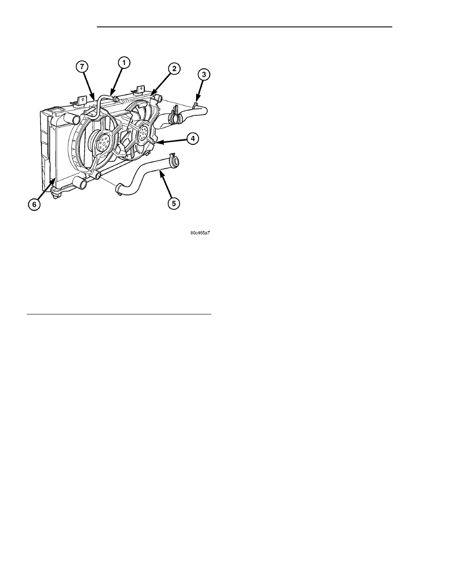
Fig. 26 UPPER AND LOWER RADIATOR HOSES -

2.5L SHOWN

1 - COOLANT BYPASS HOSE
2 - RADIATOR ASSEMBLY
3 - UPPER RADIATOR HOSE
4 - COOLING FAN
5 - LOWER RADIATOR HOSE
6 - CHARGE AIR COOLER
7 - RADIATOR BRACKET

7a - 28

ENGINE

RG

COOLANT SYSTEM HOSES (Continued)

ELECTRONIC CONTROL MODULES

TABLE OF CONTENTS

page

page

ENGINE CONTROL MODULE

DESCRIPTION

. . . . . . . . . . . . . . . . . . . . . . . . . . 1

OPERATION

. . . . . . . . . . . . . . . . . . . . . . . . . . . . 1

STANDARD PROCEDURE - PCM/ECM/SKIM

PROGRAMMING - DIESEL

. . . . . . . . . . . . . . . 2

REMOVAL

. . . . . . . . . . . . . . . . . . . . . . . . . . . . . 4

INSTALLATION

. . . . . . . . . . . . . . . . . . . . . . . . . . 4

ENGINE CONTROL MODULE

DESCRIPTION

The ECM is located in the left front corner of the

engine compartment attached to the radiator support
(Fig. 1).

OPERATION

The ECM has been programmed to monitor differ-

ent circuits of the diesel fuel injection system. This
monitoring is called on-board diagnostics. Certain cri-
teria must be met for a diagnostic trouble code to be

entered into the ECM memory. The criteria may be a
range of: engine rpm, engine temperature, time or
other input signals to the ECM. If all of the criteria
for monitoring a system or circuit are met, and a
problem is sensed, then a DTC will be stored in the
ECM memory. It is possible that a DTC for a moni-
tored circuit may not be entered into the ECM mem-
ory, even though a malfunction has occurred. This
may happen when the monitoring criteria have not
been met. The ECM compares input signal voltages
from each input device with specifications (the estab-
lished high and low limits of the input range) that
are programmed into it for that device. If the input
voltage is not within the specifications and other
trouble code criteria are met, a DTC will be stored in
the ECM memory.

ECM OPERATING MODES

As input signals to the ECM change, the ECM

adjusts its response to the output devices. For exam-
ple, the ECM must calculate a different fuel quantity
and fuel timing for engine idle condition than it
would for a wide open throttle condition. There are
several different modes of operation that determine
how the ECM responds to the various input signals.

Ignition Switch On (Engine Off)

When the ignition is turned on, the ECM activates

the glow plug relay for a time period that is deter-
mined by engine coolant temperature, atmospheric
temperature and battery voltage.

Engine Start-Up Mode

The ECM uses the engine temperature sensor and

the crankshaft position sensor (engine speed) inputs
to determine fuel injection quantity.

Normal Driving Modes

Engine idle, warm-up, acceleration, deceleration

and wide open throttle modes are controlled based on
all of the sensor inputs to the ECM. The ECM uses
these sensor inputs to adjust fuel quantity and fuel
injector timing.

Fig. 1 ENGINE CONTROL MODULE LOCATION-

TYPICAL

1 - BATTERY
2 - IPM (INTEGRATED POWER MODULE)
3 - ECM (ENGINE CONTROL MODULE)
4 - RETAINING BOLT
5 - RADIATOR SUPPORT
6 - CLUTCH CABLE BRACKET (LHD)
7 - CLUTCH CABLE BRACKET RETAINING BOLT (LHD)

RG

ELECTRONIC CONTROL MODULES

8Ea - 1

Limp-In Mode

If there is a fault detected with the accelerator

pedal position sensor, the ECM will set the engine
speed at 1100 RPM.

Overspeed Detection Mode

If the ECM detects engine RPM that exceeds 5200

RPM, the ECM will set a DTC in memory and illu-
minate the MIL until the DTC is cleared.

After-Run Mode

The ECM transfers RAM information to ROM and

performs an Input/Output state check.

MONITORED CIRCUITS

The ECM is able to monitor and identify most

driveability related trouble conditions. Some circuits
are directly monitored through ECM feedback cir-
cuitry. In addition, the ECM monitors the voltage
state of some circuits and compares those states with
expected values. Other systems are monitored indi-
rectly when the ECM conducts a rationality test to
identify problems. Although most subsytems of the
engine control module are either directly or indirectly
monitored, there may be occasions when diagnostic
trouble codes are not immediately identified. For a
trouble code to set, a specific set of conditions must
occur and unless these conditions occur, a DTC will
not set.

DIAGNOSTIC TROUBLE CODES

Each diagnostic trouble code (DTC) is diagnosed by

following a specific procedure. The diagnostic test
procedure contains step-by-step instruction for deter-
mining the cause of the DTC as well as no trouble
code problems. Refer to the appropriate Diesel Pow-
ertrain Diagnostic Manual for more information.

HARD CODE

A DTC that comes back within one cycle of the

ignition key is a hard code. This means that the
problem is current every time the ECM/SKIM checks
that circuit or function. Procedures in this manual
verify if the DTC is a hard code at the beginning of
each test. When the fault is not a hard code, an
intermittent test must be performed. NOTE: If the
DRBIII

t displays faults for multiple components (i.e.

ECT, VSS, IAT sensors) identify and check the
shared circuits for possible problems before continu-
ing (i.e. sensor grounds or 5-volt supply circuits).
Refer to the appropriate schematic to identify shared
circuits. Refer to the appropriate Diesel Powertrain
Diagnostic Manual for more information.

INTERMITTENT CODE

A DTC that is not current every time the ECM/

SKIM checks the circuit or function is an intermit-
tent code. Most intermittent DTCs are caused by
wiring or connector problems. Problems that come
and go like this are the most difficult to diagnose;
they must be looked for under specific conditions that
cause

them.

NOTE:

Electromagnetic

(radio)

interference can cause an intermittent system
malfunction. 
This interference can interrupt com-
munication between the ignition key transponder and
the SKIM. The following checks may assist you in
identifying a possible intermittent problem:

• Visually inspect the related wire harness connec-

tors. Look for broken, bent, pushed out or corroded
terminals.

• Visually inspect the related wire harness. Look

for chafed, pierced or partially broken wire.

• Refer to hotlines or technical service bulletins

that may apply.

Refer to the appropriate Diesel Powertrain Diag-

nostic Manual for more information.

ECM DIAGNOSTIC TROUBLE CODES

IMPORTANT NOTE: Before replacing the ECM for

a failed driver, control circuit or ground circuit, be
sure to check the related component/circuit integrity
for failures not detected due to a double fault in the
circuit. Most ECM driver/control circuit failures are
caused by internal failures to components (i.e. relays
and solenoids) and shorted circuits (i.e. sensor pull-
ups, drivers and ground circuits). These faults are
difficult to detect when a double fault has occurred
and only one DTC has set. If the DRBIII

t displays

faults for multiple components (i.e.VSS, ECT, Batt
Temp, etc.) identify and check the shared circuits for
possible

problems

before

continuing

(i.e.

sensor

grounds or 5-volt supply circuits). Refer to the appro-
priate wiring diagrams to identify shared circuits.
Refer to the appropriate Diesel Powertrain Diagnos-
tic Manual for more information.

STANDARD PROCEDURE - PCM/ECM/SKIM
PROGRAMMING - DIESEL

NOTE: Before replacing the PCM/ECM for a failed
driver, control circuit or ground circuit, be sure to
check the related component/circuit integrity for
failures not detected due to a double fault in the cir-
cuit. Most PCM/ECM driver/control circuit failures
are caused by internal component failures (i.e. relay
and solenoids) and shorted circuits (i.e. pull-ups,
drivers and switched circuits). These failures are
difficult to detect when a double fault has occurred
and only one DTC has set.

8Ea - 2

ELECTRONIC CONTROL MODULES

RG

ENGINE CONTROL MODULE (Continued)

PCM/SKIM PROGRAMMING

When a PCM (JTEC) and the SKIM are replaced

at the same time perform the following steps in
order:

(1) Program the new PCM (JTEC)
(2) Program the new SKIM
(3) Replace all ignition keys and program them to

the new SKIM.

ECM/SKIM PROGRAMMING

When an ECM (Bosch) and the SKIM are replaced

at the same time perform the following steps in
order:

(1) Program the new SKIM
(2) Program the new ECM (Bosch)

PROGRAMMING THE ECM (Bosch)

(1) To program the VIN, connect the DRB III

t and

turn the ignition on.

(2) Select Engine from the main menu. The DRB

III

t will require the VIN to be entered before con-

tinuing.

(3) Select ENTER to update the VIN. The DRB

III

t will display the updated VIN.

(4) If the engine is equipped with air conditioning,

the ECM A/C function must be enabled. Enable the
ECM A/C function as follows:

• Using the DRB IIIt select ENGINE, MISCEL-

LANEOUS, then ENABLE/DISABLE A/C

• Push 1 to enable A/C. DRB IIIt screen should

display A/C Activated.

PROGRAMMING THE PCM (JTEC)

The SKIS Secret Key is an ID code that is unique

to each SKIM. This code is programmed and stored
in the SKIM, PCM and transponder chip (ignition
keys). When replacing the PCM it is necessary to
program the secret key into the new PCM using the
DRB III

t. Perform the following steps to program the

secret key into the PCM.

(1) Turn the ignition switch on (transmission in

park/neutral).

(2) Use the DRB III

t and select THEFT ALARM,

SKIM then MISCELLANEOUS.

(3) Select PCM REPLACED (GAS ENGINE).
(4) Enter secured access mode by entering the

vehicle four-digit PIN.

(5) Select ENTER to update PCM VIN.

NOTE: If three attempts are made to enter secure
access mode using an incorrect PIN, secured
access mode will be locked out for one hour. To
exit this lockout mode, turn the ignition to the RUN
position for one hour then enter the correct PIN.
(Ensure all accessories are turned off. Also monitor

the battery state and connect a battery charger if
necessary).

(6) Press ENTER to transfer the secret key (the

SKIM will send the secret key to the PCM).

(7) Press Page Back to get to the Select System

menu and select ENGINE, JTEC (diesel only), MIS-
CELLANEOUS, and SRI MEMORY CHECK.

(8) The DRB III

t will ask, Is odometer reading

between XX and XX? Select the YES or NO button on
the DRB III

t. If NO is selected, the DRB IIIt will

read, Enter odometer Reading<From I.P. odometer>.
Enter the odometer reading from the Instrument
Panel and press ENTER.

PROGRAMMING THE SKIM

(1) Turn the ignition switch on (transmission in

park/neutral).

(2) Use the DRB III

t and select THEFT ALARM,

SKIM then MISCELLANEOUS.

(3) Select PCM REPLACED (GAS ENGINE).
(4) Program the vehicle four-digit PIN into SKIM.
(5) Select COUNTRY CODE and enter the correct

country.

NOTE: Be sure to enter the correct country code. If
the incorrect country code is programmed into
SKIM, the SKIM must be replaced.

(6) Select YES to update VIN (the SKIM will learn

the VIN from the PCM).

(7) Press ENTER to transfer the secret key (the

PCM will send the secret key to the SKIM).

(8) Program ignition keys to SKIM.

NOTE: If the PCM and the SKIM are replaced at the
same time, all vehicle keys will need to be replaced
and programmed to the new SKIM.

PROGRAMMING IGNITION KEYS TO THE SKIM

(1) Turn the ignition switch on (transmission in

park/neutral).

(2) Use the DRB III

t and select THEFT ALARM,

SKIM then MISCELLANEOUS.

(3) Select PROGRAM IGNITION KEY’S.
(4) Enter secured access mode by entering the

vehicle four-digit PIN.

NOTE: A maximum of eight keys can be learned to
each SKIM. Once a key is learned to a SKIM it (the
key) cannot be transferred to another vehicle.

If ignition key programming is unsuccessful, the

DRB III

t will display one of the following messages:

Programming Not Attempted - The DRB III

t

attempts to read the programmed key status and
there are no keys programmed into SKIM memory.

RG

ELECTRONIC CONTROL MODULES

8Ea - 3

ENGINE CONTROL MODULE (Continued)


Content   ..  463  464  465  466   ..