Content .. 1249 1250 1251 1252 ..
Chrysler RG Voyager. Manual - part 1251
3.4
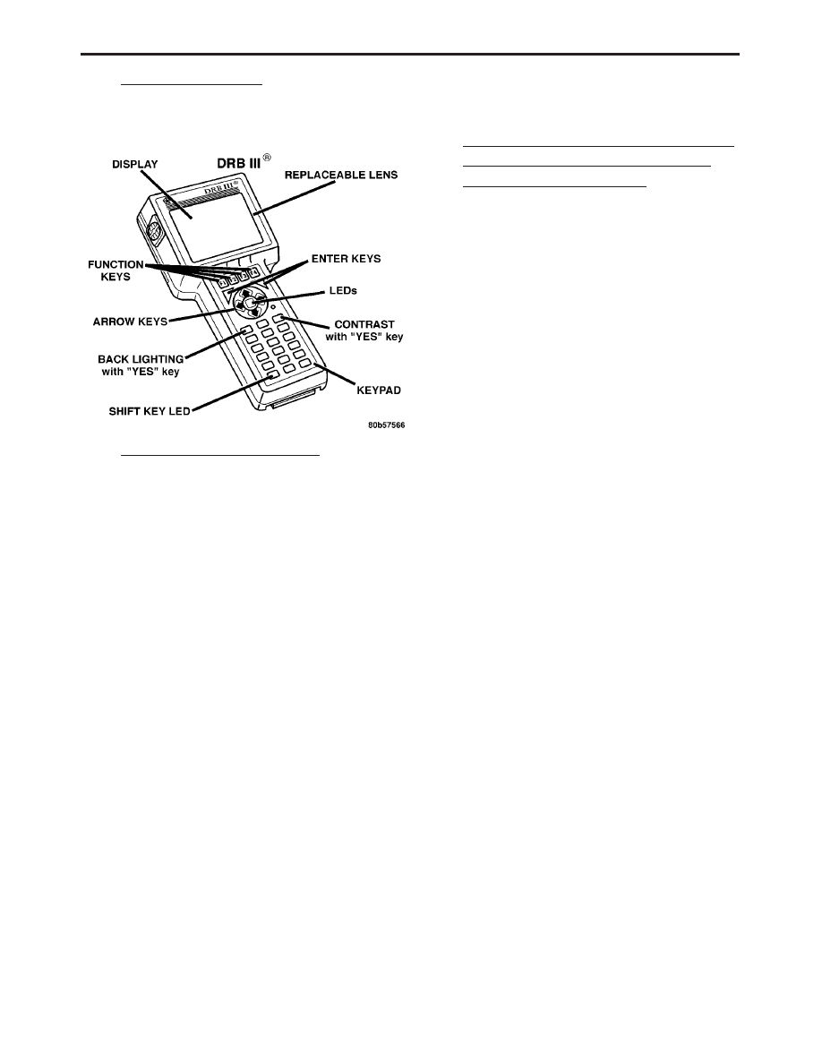
USING THE DRBIII
T
Refer to the DRBIII
t users guide for instructions
and assistance with reading trouble codes, erasing
trouble codes, and other DRBIII
t functions.
3.5
DRBIII
T ERROR MESSAGES
Under normal operation, the DRBIII
t will dis-
play one of only two error messages:
User-Requested WARM Boot
User-Requested COLD Boot
If the DRBIII
t should display any other error
message, record the entire display and call the
S.T.A.R. Center.
3.5.1
DRBIII
T DOES NOT POWER UP
(BLANK SCREEN)
If the LED’s do not light or no sound is emitted at
start up, check for loose cable connections or a bad
cable. Check the vehicle battery voltage. A mini-
mum of 11 volts is required to adequately power the
DRBIII
t.
If all connections are proper between the
DRBIII
t and the vehicle or other devices, and the
vehicle battery is fully charged, an inoperative
DRBIII
t may be the result of faulty cable or vehicle
wiring. For a blank screen, refer to the appropriate
Body Diagnostic manual.
3.5.2
DISPLAY IS NOT VISIBLE
Low temperatures will affect the visibility of the
display. Adjust the contrast to compensate for this
condition.
3.5.3
SOME DISPLAY ITEMS READ
(---(
This is caused by the scrolling the DRBIII
t dis-
play a single line up or down. The line which was
scrolled onto the screen might read
9---9. Use the
page down or page up function to display the
information.
3.6
TRANSMISSION SIMULATOR (MILLER
TOOL # 8333) AND FWD ADAPTER
(MILLER TOOL #8333-1A)
NOTE: Remove the starter Relay when using
the transmission simulator
*Failure to remove the Starter Relay can
cause a PCM - No Response condition.
*The removal of the Starter Relay will also
prevent the engine from starting in gear.
*The
Transmission
Simulator
will
not
accurately diagnose intermittent faults.
The transmission simulator, simply put, is an
electronic device that simulates the electronic func-
tions of any EATX or NGC controlled transmission
(41TE, 41TE, 45RFE, and 545RFE). The basic func-
tion of the simulator is to aid the technician in
determining if an internal transmission problem
exists or if the problem resides in the vehicle wiring
or control module. It is only useful for electrical
problems. It will not aid in the diagnosis of a failed
mechanical component, but it can tell you if the
control module and wiring are working properly
and that the problem is internal to the transmis-
sion.
The ignition switch should be in the lock position
before attempting to install the simulator. Follow
all instructions included with the simulator. If the
feedback from the simulator is in doubt, you can
verify the simulators operation by installing it on a
known good vehicle. A
9known good vehicle9 would
be defined as a vehicle that does not set any DTC’s
and drives and shifts as expected.
One important point to remember is that the
Simulator receives power from the Trans Relay
Output circuit. If the transmission system is in
Limp-in (Relay open), the simulator will not oper-
ate. This is not really an indication of a problem,
but an additional symptom. If the simulator does
not power up (
9P9 led lit), this is an indication that
the problem is still present with the simulator
hooked up. This indicates that the problem is in the
wiring or control module and not the transmission.
Miller Tool # 8333-1A consists of the adapter
cables and overlay necessary to adapt the simulator
to TE/AE/RLE/LE transmissions.
5
GENERAL INFORMATION