Chrysler RG Voyager. Manual - part 1224


  Index      Chrysler     Chrysler RG Voyager - service repair manual 2005 year


Search            


Content   ..  1222  1223  1224  1225   ..


Chrysler RG Voyager. Manual - part 1224


DISTRIBUTION - REAR

TABLE OF CONTENTS

page

page

AIR OUTLETS

REMOVAL

. . . . . . . . . . . . . . . . . . . . . . . . . . . . . 61

INSTALLATION

. . . . . . . . . . . . . . . . . . . . . . . . . 61

DISTRIBUTION DUCT

REMOVAL

. . . . . . . . . . . . . . . . . . . . . . . . . . . . . 61

INSTALLATION

. . . . . . . . . . . . . . . . . . . . . . . . . 62

BLOWER MOTOR

DESCRIPTION

. . . . . . . . . . . . . . . . . . . . . . . . . 62

OPERATION

. . . . . . . . . . . . . . . . . . . . . . . . . . . 62

REMOVAL

. . . . . . . . . . . . . . . . . . . . . . . . . . . . . 62

INSTALLATION

. . . . . . . . . . . . . . . . . . . . . . . . . 63

HVAC HOUSING

REMOVAL

. . . . . . . . . . . . . . . . . . . . . . . . . . . . . 63

INSTALLATION

. . . . . . . . . . . . . . . . . . . . . . . . . 65

REAR FLOOR HEAT DUCT

REMOVAL

. . . . . . . . . . . . . . . . . . . . . . . . . . . . . 66

INSTALLATION

. . . . . . . . . . . . . . . . . . . . . . . . . 66

AIR OUTLETS

REMOVAL

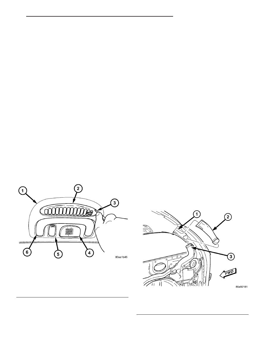
(1) Using a trim stick C-4755 or equivalent, disen-

gage the thumb wheel end of the overhead air outlet
from the pivot pin in the headliner bezel (Fig. 1).

(2) Disengage the opposite end of the overhead air

outlet from the pivot pin in the headliner bezel and
remove the air outlet.

INSTALLATION

(1) Position the overhead air outlet into the open-

ing in the headliner bezel.

(2) Engage the non-thumb wheel end of the over-

head air outlet onto the pivot pin in the headliner
bezel.

(3) Using hand pressure, push the thumb wheel

end of the overhead air outlet onto the pivot pin until
fully engaged.

DISTRIBUTION DUCT

REMOVAL

(1) Remove the trim panels from the inner right

quarter panel and the right D-pillar (Refer to 23 -
BODY/INTERIOR/RIGHT QUARTER TRIM PANEL
- REMOVAL).

(2) Slide the rear distribution duct upwards and

disengage it from the outlet located at the top of the
rear HVAC housing (Fig. 2).

(3) While pulling the lower end of the rear distri-

bution duct away from the rear HVAC housing, dis-

Fig. 1 Overhead Outlet

1 - HEADLINER BEZEL
2 - OVERHEAD AIR OUTLET
3 - TRIM STICK
4 - COURTESY LAMP
5 - COAT HOOK
6 - ASSIST HANDLE

Fig. 2 Rear Distribution Duct

1 - HEADLINER DUCT
2 - REAR DISTRIBUTION DUCT
3 - REAR HVAC HOUSING

RS

DISTRIBUTION - REAR

24 - 61

engage the upper end of the distribution duct from
the headliner duct and remove the duct.

INSTALLATION

(1) Position the upper end of the rear distribution

duct to the headliner duct.

(2) Install the upper end of the rear distribution

duct onto the headliner duct and align the lower end
of the duct with the outlet at the top of the rear
HVAC housing.

(3) Slide the rear distribution duct downward and

engage it onto the outlet located at the top of the
rear HVAC housing.

(4) Install the trim panels onto the inner right

quarter panel and the right D-pillar (Refer to 23 -
BODY/INTERIOR/RIGHT QUARTER TRIM PANEL
- INSTALLATION).

BLOWER MOTOR

DESCRIPTION

The blower motor for the rear heating-A/C system

is a 12-volt, direct current (DC) motor with an inte-
gral wire harness and connector that is mounted
within a plastic housing with a squirrel cage-type
blower wheel, which is secured to the blower motor
shaft (Fig. 3). The blower motor and wheel is located
on the outboard side of the rear HVAC housing.

The blower motor can be accessed for service by

removing the rear HVAC housing.

OPERATION

The rear blower motor is used to control the veloc-

ity of air moving through the rear HVAC housing by
spinning the blower wheel within the housing at the
selected or programed speed (depending on applica-
tion).

On models equipped with the manual temperature

control (MTC) heating-A/C system, the rear blower
motor will operate only whenever the ignition switch
is in the On position, the front blower control switch
is in any position except Off and the rear blower con-
trol switch on the front A/C-heater control is in any
position except Off. On models equipped with the
automatic temperature control (ATC) heating-A/C
system, the blower motor will operate whenever the
ignition switch is in the On position, the A/C-heater
control power is turned on and the rear blower con-
trol switch on the front A/C-heater control is in any
position except Off. The rear blower motor can only
be turned off by turning off the rear system at the
front A/C-heater control.

The rear blower motor relay output circuit is pro-

tected by a fuse in the integrated power module
(IPM) located in the engine compartment. In the
MTC system, the rear blower motor speed is con-
trolled by regulating the path to ground through the
blower control switch and the blower motor resistor.
In the ATC system, the rear blower motor speed is
controlled by an electronic blower motor power mod-
ule, which uses a pulse width modulated input from
the A/C-heater control and a feedback signal from the
rear blower motor to regulate the blower motor
ground path. The rear blower motor receives battery
current whenever the rear blower motor relay is
energized.

For diagnosis and testing of the rear blower motor,

refer to 24 - HEATING & AIR CONDITIONING/DIS-
TRIBUTION - FRONT/BLOWER MOTOR - DIAG-
NOSIS AND TESTING.

The rear blower motor and blower motor wheel are

factory balanced and cannot be adjusted or repaired.
If faulty or damaged, the rear blower motor and
blower wheel must be replaced as an assembly.

REMOVAL

WARNING: Refer to the applicable warnings and
cautions for this system before performing the fol-
lowing operation (Refer to 24 - HEATING & AIR
CONDITIONING/PLUMBING - FRONT - WARNINGS)
and (Refer to 24 - HEATING & AIR CONDITIONING/
PLUMBING - FRONT - CAUTIONS). Failure to follow
the warnings and cautions could result in possible
personal injury or death.

Fig. 3 Rear Blower Motor

1 - REAR BLOWER MOTOR
2 - WIRE HARNESS AND CONNECTOR
3 - BLOWER MOTOR WHEEL
4 - BLOWER MOTOR SHAFT

24 - 62

DISTRIBUTION - REAR

RS

DISTRIBUTION DUCT (Continued)

(1) Remove the rear HVAC housing and place it on

a workbench (Refer to 24 - HEATING & AIR CON-
DITIONING/DISTRIBUTION - REAR/HVAC HOUS-
ING - REMOVAL).

NOTE: On the manual temperature control (MTC)
heating-A/C system, the rear blower motor wire har-
ness is connected to the rear HVAC wire harness.
On the automatic temperature control (ATC) heat-
ing-A/C system, the rear blower motor wire harness
is connected to the rear blower motor power mod-
ule.

(2) Disconnect the wire harness connector for the

rear blower motor (Fig. 4).

(3) Remove the three screws that secure the rear

blower motor to the outboard side of the rear HVAC
housing and remove the blower motor.

INSTALLATION

(1) Position the rear blower motor onto the rear

HVAC housing.

(2) Install the three screws that secure the rear

blower motor to the rear HVAC housing. Tighten the
screws to 2 N·m (17 in. lbs.).

NOTE: On the manual temperature control (MTC)
heating-A/C system, the rear blower motor wire har-
ness is connected to the rear HVAC wire harness.
On the automatic temperature control (ATC) heat-
ing-A/C system, the rear blower motor wire harness
is connected to the rear blower motor power mod-
ule.

(3) Connect the wire harness connector for the

rear blower motor.

(4) Install the rear HVAC housing (Refer to 24 -

HEATING & AIR CONDITIONING/DISTRIBUTION
- REAR/HVAC HOUSING - INSTALLATION).

HVAC HOUSING

REMOVAL

WARNING: Refer to the applicable warnings and
cautions for this system before performing the fol-
lowing operation (Refer to 24 - HEATING & AIR
CONDITIONING/PLUMBING - FRONT - WARNINGS)
and (Refer to 24 - HEATING & AIR CONDITIONING/
PLUMBING - FRONT - CAUTIONS). Failure to follow
the warnings and cautions could result in possible
personal injury or death.

NOTE: The rear HVAC housing must be removed
from the vehicle and disassembled for service of
the A/C evaporator and the mode/blend-air door.

(1) Recover the refrigerant from the refrigerant

system (Refer to 24 - HEATING & AIR CONDITION-
ING/PLUMBING - FRONT - STANDARD PROCE-
DURE - REFRIGERANT RECOVERY).

(2) Drain the engine cooling system (Refer to 7 -

COOLING - STANDARD PROCEDURE - COOLING
SYSTEM DRAIN).

(3) Disconnect and isolate the negative battery

cable.

(4) Raise and support the vehicle.
(5) Remove the nut that secures the underbody

refrigerant line sealing plate to the rear evaporator
extension line tapping plate that extends through the
rear floor panel behind the right rear wheel housing
(Fig. 5) and (Fig. 6).

(6) Disconnect the underbody refrigerant lines

from the rear evaporator extension line tapping plate
and remove and discard the O-ring seals.

Fig. 4 Rear Blower Motor

1 - REAR HVAC HOUSING
2 - REAR BLOWER MOTOR
3 - SCREW (3)
4 - BLOWER MOTOR WIRE HARNESS

RS

DISTRIBUTION - REAR

24 - 63

BLOWER MOTOR (Continued)

(7) Install plugs in, or tape over the opened under-

body refrigerant line fittings and the evaporator
extension line sealing plate ports.

(8) Remove the nuts from the mounting studs that

secure the rear HVAC housing to the rear floor panel
behind the right rear wheel housing (Fig. 7).

(9) Lower the vehicle.
(10) Remove the trim panels from the inner right

quarter panel and the right D-pillar (Refer to 23 -
BODY/INTERIOR/RIGHT QUARTER TRIM PANEL
- REMOVAL).

(11) Remove the rear distribution duct from the

rear HVAC housing and the rear headliner duct
(Refer to 24 - HEATING & AIR CONDITIONING/
DISTRIBUTION

-

REAR/AIR

OUTLETS

-

REMOVAL).

(12) Disconnect the body wire harness connector

for the rear HVAC housing from the rear HVAC wire
harness connector located near the A/C expansion
valve.

(13) Remove the two screws that secure the top of

the quarter trim panel attaching bracket to the inner
quarter panel.

(14) Remove the two screws that secure the bottom

of the quarter trim panel attaching bracket to the
rear HVAC housing.

(15) Remove the rear floor heat duct from the

inner right quarter panel (Refer to 24 - HEATING &
AIR

CONDITIONING/DISTRIBUTION

-

REAR/

REAR FLOOR HEAT DUCT - REMOVAL).

NOTE: Use absorbent toweling to clean up any
engine coolant spills.

(16) Disconnect the heater hoses at the rear heater

core (Refer to 24 - HEATING & AIR CONDITION-
ING/PLUMBING

-

REAR/HEATER

HOSE

-

REMOVAL).

(17) Install plugs in, or tape over the opened

heater core fittings and both heater hoses.

Fig. 5 Underbody A/C Line Rear Connections – with

New Seating Element (NSE)

1 - UNDERBODY LIQUID LINE
2 - NUT
3 - SEALING PLATE
4 - UNDERBODY SUCTION LINE
5 - EXTENSION LINE TAPPING PLATE

Fig. 6 Underbody A/C Line Rear Connections –

without New Seating Element (NSE)

1 - UNDERBODY LIQUID LINE
2 - BOLT
3 - EXTENSION LINE TAPPING PLATE
4 - UNDERBODY SUCTION LINE
5 - SEALING PLATE

Fig. 7 Rear HVAC Housing Mounting Studs –

Typical

1 - REAR HVAC HOUSING MOUNTING STUDS

24 - 64

DISTRIBUTION - REAR

RS

HVAC HOUSING (Continued)


Content   ..  1222  1223  1224  1225   ..