Chrysler RG Voyager. Manual - part 1223


  Index      Chrysler     Chrysler RG Voyager - service repair manual 2005 year


Search            


Content   ..  1221  1222  1223  1224   ..


Chrysler RG Voyager. Manual - part 1223


(6) Disengage the HVAC wire harness from the

routing clips on the HVAC housing and remove the
wire harness from the housing.

(7) If required, remove three screws that secure

the blower motor to the HVAC housing and remove
the blower motor.

(8) If required, remove two screws that secure the

blower motor resistor or power module (depending on
application) to the HVAC housing and remove the
resistor or module.

(9) If required, remove two screws that secure the

support bracket to the HVAC housing and remove
the bracket.

(10) Remove the thirteen screws that secure the

upper HVAC housing half to the lower half of the
HVAC housing.

(11) Separate the two halves of the HVAC housing.
(12) Carefully lift the A/C evaporator and insulator

out of the lower half of the HVAC housing.

ASSEMBLY

AIR DISTRIBUTION HOUSING

NOTE:

The

air

distribution

housing

must

be

removed from the HVAC housing and disassembled
for service of the mode-air and blend-air doors.

(1) Install the air doors into the passenger side of

the air distribution housing as required. Align the air
doors with the pivot shaft holes in the housing.

(2) Install the air vane and retaining screw to the

passenger side of the air distribution housing.
Tighten the screw to 2 N·m (17 in. lbs.).

(3) Align the air door pivot shafts with the pivot

holes in the center partition and install the partition
onto the passenger side of the air distribution hous-
ing.

(4) Install the driver side air vane and retaining

screw to the center partition. Tighten the screw to 2
N·m (17 in. lbs.).

(5) Install the blend-air door to the driver side of

the air distribution housing. Align the air door with
the pivot shaft hole in the housing.

(6) If equipped with dual zone heating-A/C system,

align and install the blend door gear into the pivot
shaft of the driver side blend-air door. Make sure
that the retaining tab on the door gear is securely
engaged to the pivot shaft.

(7) Align the air door pivot shafts to each other

and carefully install the driver side half of the air
distribution housing to the passenger side half of the
housing.

(8) Install the seven screws that secure the two

halves of the air distribution housing together.
Tighten the screws to 2 N·m (17 in. lbs.).

(9) Inspect the foam seal, especially at the parting

line. If the seal is deformed or damaged, it must be
replaced.

(10) Install the screw to the center of the driver

side air distribution housing. Tighten the screw to 2
N·m (17 in. lbs.).

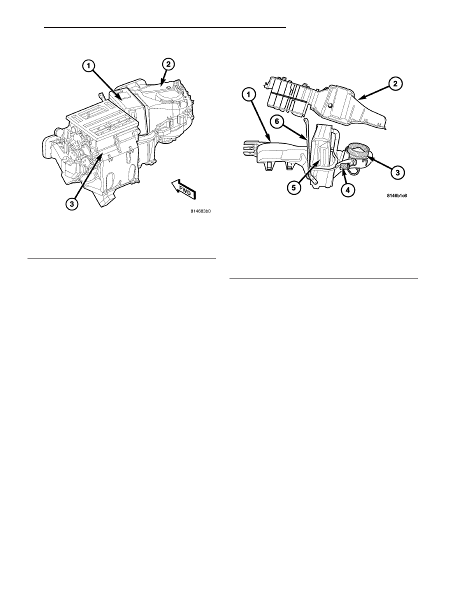
Fig. 27 HVAC Housing Assembly

1 - HVAC HOUSING
2 - AIR INLET HOUSING
3 - AIR DISTRIBUTION HOUSING

Fig. 28 HVAC Housing

1 - LOWER HVAC HOUSING
2 - UPPER HVAC HOUSING
3 - BLOWER MOTOR
4 - BLOWER MOTOR RESISTOR/POWER MODULE
5 - A/C EVAPORATOR
6 - SUPPORT BRACKET

RS

DISTRIBUTION - FRONT

24 - 57

HVAC HOUSING (Continued)

(11) Position the floor distribution ducts onto the

air distribution housing.

(12) Install the six screws that secure the floor dis-

tribution ducts to the air distribution housing.
Tighten the screws to 2 N·m (17 in. lbs.).

NOTE: Align the guide pin on the linkage arms with
the guides on the mode door cam during installa-
tion of the floor door gear and linkage arms.

(13) Install the passenger side blend door stop,

driver side blend door gear (if equipped), floor door
gear, mode door cam, instrument panel door linkage
arm and the defrost door linkage arm onto the driver
side of the air distribution housing.

(14) Position the mode door and blend door actua-

tors onto the driver side of the air distribution hous-
ing. If necessary, rotate the actuators slightly to align
the splines on the actuator output shaft with those in
the air door linkage.

(15) Install the two screws that secure each actua-

tor to the air distribution housing. Tighten the
screws to 2 N·m (17 in. lbs.).

(16) Carefully install the heater core into the

driver side of the air distribution housing.

(17) Install the two screws that secure the heater

core to the air distribution housing. Tighten the
screw to 2 N·m (17 in. lbs.).

(18) Install the air distribution housing onto the

HVAC housing (Refer to 24 - HEATING & AIR CON-
DITIONING/DISTRIBUTION

-

FRONT/HVAC

HOUSING

- AIR

DISTRIBUTION

HOUSING

-

INSTALLATION).

HVAC HOUSING

(1) Install the A/C evaporator into the lower half of

the HVAC housing. Make sure that the evaporator
drain within the HVAC housing is clean and unre-
stricted and that the insulator around the A/C evap-
orator is properly installed.

(2) Install the upper half of the HVAC housing

onto the lower half of the HVAC housing.

(3) Install the thirteen screws that secure the two

halves of the HVAC housing together. Tighten the
screws to 2 N·m (17 in lbs.).

(4) If removed, install the support bracket and the

two retaining screws. Tighten the screws to 2 N·m
(17 in lbs.).

(5) If removed, install the blower motor resistor or

power module (depending on application) and the two
retaining screws. Tighten the screws to 2 N·m (17 in
lbs.).

(6) If removed, install the blower motor and the

three retaining screws. Tighten the screws to 2 N·m
(17 in lbs.).

(7) Install the HVAC wiring harness. Make sure

the harness is routed through all wiring retainers.

(8) Engage the HVAC wire harness into the rout-

ing clips on the HVAC housing.

(9) Connect the HVAC wire harness connector to

the blower motor resistor or power module (depend-
ing on application).

(10) Install the A/C expansion valve (Refer to 24 -

HEATING & AIR CONDITIONING/PLUMBING -
FRONT/A/C

EXPANSION

VALVE

-

INSTALLA-

TION).

(11) Install the air inlet housing onto the HVAC

housing (Refer to 24 - HEATING & AIR CONDI-
TIONING/DISTRIBUTION - FRONT/HVAC HOUS-
ING - AIR INLET HOUSING - INSTALLATION).

(12) Install the air distribution housing onto the

HVAC housing (Refer to 24 - HEATING & AIR CON-
DITIONING/DISTRIBUTION

-

FRONT/HVAC

HOUSING

- AIR

DISTRIBUTION

HOUSING

-

INSTALLATION).

(13) Install the HVAC housing into the vehicle

(Refer to 24 - HEATING & AIR CONDITIONING/
DISTRIBUTION

-

FRONT/HVAC

HOUSING

-

INSTALLATION).

INSTALLATION

AIR DISTRIBUTION HOUSING

NOTE:

The

air

distribution

housing

must

be

removed from the HVAC housing and disassembled
for service of the mode-air and blend-air doors.

(1) Install the air distribution housing onto the

rear of the HVAC housing by inserting the two tabs
on the bottom of the distribution housing into the
slots located on the bottom of the HVAC housing and
tipping the distribution housing forward until it is
properly aligned with the HVAC housing.

(2) Install the four screws that secure the air dis-

tribution housing to the HVAC housing. Tighten the
screws to 2 N·m (17 in. lbs.).

(3) Remove the tape or plugs from the heater core

ports.

(4) Lubricate new rubber O-ring seals with clean

engine coolant and install them onto the heater core
tube fittings. Use only the specified O-ring as they
are made of a special material for the engine cooling
system.

(5) Position both heater core tubes and the sealing

plate simultaneously onto the heater core.

24 - 58

DISTRIBUTION - FRONT

RS

HVAC HOUSING (Continued)

NOTE: The heater core tubes each have a slot that
must be indexed to a location tab within each of the
heater core ports. Adjust the position of the tubes
as required so that the sealing plate fits flush
against the heater core supply and return ports,
which indicates that the tubes are properly indexed.

(6) Index both heater core tubes to the heater core

ports.

(7) Install the bolt that secures the heater core

tube sealing plate to the heater core. Tighten the bolt
to 3 N·m (27 in. lbs.).

(8) Install the plastic retaining clamp that secures

the heater core tubes to the front of the HVAC hous-
ing.

(9) Install the foam seal onto the heater core tubes

and the flange located at the front of the HVAC hous-
ing.

(10) Position the HVAC wire harness onto the air

distribution housing.

(11) Connect the HVAC wire harness connectors to

the mode door actuator and the blend door actua-
tor(s) located on the driver side of the air distribution
housing.

(12) Install the HVAC housing assembly (Refer to

24 - HEATING & AIR CONDITIONING/DISTRIBU-
TION - FRONT/HVAC HOUSING - INSTALLA-
TION).

AIR INLET HOUSING

NOTE: The air inlet housing must be removed from
HVAC housing for service of the recirculation-air
door.

(1) If removed, install the recirculation-air door

into the upper air inlet housing and install the
retaining screw. Tighten the screw to 2 N·m (17 in.
lbs.).

(2) Position the air inlet housing and recirculation-

air door onto the HVAC housing.

CAUTION: Make sure that the recirculation-air door
pivot shaft is properly seated in the pivot seats.

(3) Install the three screws that secure the upper

air inlet housing to the HVAC housing. Tighten the
screws to 2 N·m (17 in. lbs.).

(4) Inspect the foam seal along the parting line. If

the seal is deformed or damaged, it must be replaced.

(5) Feed the blower motor wire lead through the

opening in the lower air inlet housing and seat the
rubber grommet into the lower air inlet housing.

(6) Position the recirculation-air door pivot into

the lower air inlet housing.

(7) Install the four screws (from the bottom) that

secure the lower air inlet housing to the upper air

inlet housing and the lower HVAC housing. Tighten
the screws to 2 N·m (17 in. lbs.).

(8) Install the one screw (from the top) that

secures the lower air inlet housing to the upper air
inlet housing. Tighten the screws to 2 N·m (17 in.
lbs.).

(9) Connect the blower motor wire lead connector

to the blower motor resistor or power module,
depending on application.

(10) Install the recirculation door actuator wire

lead into the routing clip located on the lower air
inlet housing.

(11) Install the recirculation door actuator (Refer

to 24 - HEATING & AIR CONDITIONING/CON-
TROLS - FRONT/RECIRCULATION DOOR ACTUA-
TOR - INSTALLATION).

(12) Install the HVAC housing assembly (Refer to

24 - HEATING & AIR CONDITIONING/DISTRIBU-
TION - FRONT/HVAC HOUSING - INSTALLA-
TION).

HVAC HOUSING

NOTE: The HVAC housing must be removed from
the vehicle and disassembled for service of the air
inlet housing, air distribution housing and the A/C
evaporator.

(1) Position the HVAC housing against the dash

panel in the passenger compartment with the three
mounting studs located in their proper holes. Make
sure that the condensate drain tube protrudes
through its opening.

(2) Loosely install the nut and bolt that secures

the HVAC housing to the passenger compartment
side of the dash panel.

(3) Install the three nuts that secure the HVAC

housing to the engine compartment side of the dash
panel. Tighten the nuts to 7 N·m (62 in. lbs.).

(4) Tighten the nut and bolt that secures the

HVAC housing to the passenger compartment side of
the dash panel to 3 N·m (26 in. lbs.).

(5) Install the instrument panel (Refer to 23 -

BODY/INSTRUMENT

PANEL/INSTRUMENT

PANEL ASSEMBLY - INSTALLATION).

(6) Connect the heater hoses to the heater core

(Refer to 24 - HEATING & AIR CONDITIONING/
PLUMBING - FRONT/HEATER INLET HOSE -
INSTALLATION) and (Refer to 24 - HEATING &
AIR

CONDITIONING/PLUMBING

-

FRONT/

HEATER RETURN HOSE - INSTALLATION).

(7) Connect the suction and liquid lines to the A/C

expansion valve (Refer to 24 - HEATING & AIR
CONDITIONING/PLUMBING

-

FRONT/LIQUID

LINE - INSTALLATION).

(8) Reconnect the negative battery cable.

RS

DISTRIBUTION - FRONT

24 - 59

HVAC HOUSING (Continued)

(9) If the heater core is being replaced, flush the

cooling system (Refer to 7 - COOLING - STANDARD
PROCEDURE - COOLING SYSTEM CLEANING/
REVERSE FLUSHING).

(10) Refill the engine cooling system (Refer to 7 -

COOLING - STANDARD PROCEDURE - COOLING
SYSTEM REFILL).

(11) Evacuate the refrigerant system (Refer to 24 -

HEATING & AIR CONDITIONING/PLUMBING -
FRONT - STANDARD PROCEDURE - REFRIGER-
ANT SYSTEM EVACUATE).

(12) Charge the refrigerant system (Refer to 24 -

HEATING & AIR CONDITIONING/PLUMBING -
FRONT - STANDARD PROCEDURE - REFRIGER-
ANT SYSTEM CHARGE).

(13) Calibrate the A/C-heater control (Refer to 24 -

HEATING & AIR CONDITIONING/CONTROLS -
FRONT/A/C

HEATER

CONTROL

-

STANDARD

PROCEDURE -A/C-HEATER CONTROL CALIBRA-
TION).

24 - 60

DISTRIBUTION - FRONT

RS

HVAC HOUSING (Continued)


Content   ..  1221  1222  1223  1224   ..