Content .. 1145 1146 1147 1148 ..
Chrysler RG Voyager. Manual - part 1147
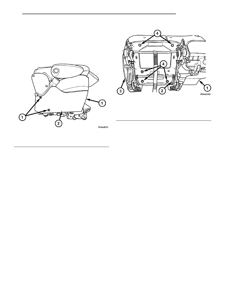
QUAD BUCKET SEAT SIDE
SHIELD - NO CUP HOLDER
REMOVAL
(1) Remove the three screws (Fig. 85).
(2) Remove the side shield.
INSTALLATION
(1) Install the side shield hook into the rectangu-
lar hole on the riser.
(2) Install the three screws.
QUAD BUCKET SEAT RISER
REMOVAL
(1) Remove the seat from vehicle. Refer to Owner’s
Manual for proper procedures.
(2) Remove seat side shield/cup holder. (Refer to 23
-
BODY/SEATS/QUAD
BUCKET
SEAT
SIDE
SHIELD/CUP HOLDER - REMOVAL)
(3) Remove the seat side shield. (Refer to 23 -
BODY/SEATS/QUAD BUCKET SEAT SIDE SHIELD
- NO CUP HOLDER - REMOVAL)
(4) Remove the five bolts, two nuts, strut bushing
and remove the riser from the seat (Fig. 86).
INSTALLATION
(1) Install the riser, the strut bushing into the
hole, the five bolts, two nuts and tighten all fasteners
to 40 N·m (30 ft. lbs.).
(2) Install the seat side shield. (Refer to 23 -
BODY/SEATS/QUAD BUCKET SEAT SIDE SHIELD
- NO CUP HOLDER - INSTALLATION)
(3) Install the seat side shield/cup holder. (Refer to
23 - BODY/SEATS/QUAD BUCKET SEAT SIDE
SHIELD/CUP HOLDER - INSTALLATION)
(4) Install the seat. Refer to Owner’s Manual for
proper procedures.
BENCH SEAT BACK PANEL
REMOVAL
(1) On third row seats remove plastic grocery bag
retainer. (Refer to 23 - BODY/SEATS/PLASTIC GRO-
CERY BAG RETAINER - REMOVAL)
(2) Using a fork type prying tool (C4829) on three
pass seats, disengage push-in fasteners holding seat
back cover to seat back frame and remove seat back
cover from seat. (Fig. 87).
(3) Using a fork type prying tool (C4829) on two
pass seats, disengage push-in fasteners holding the
upper corners and lower edge of the seat back panel
to seat back frame and remove seat back cover from
seat by pulling the lower edge out away from the
seat back to disengage the upper two hooks. (Fig. 88).
INSTALLATION
(1) On three pass seats place seat back panel in
position on seat and install the push-in fasteners
(Fig. 87).
(2) On two pass seats engage the two upper hooks
of the panel, place the panel into position and install
the push-in fasteners (Fig. 88).
(3) On third row bench seats install grocery bag
holder. (Refer to 23 - BODY/SEATS/PLASTIC GRO-
CERY BAG RETAINER - INSTALLATION)
Fig. 85 SEAT SIDE COVER - QUAD BUCKETS
1 - SIDE SHIELD SCREWS
2 - SIDE SHIELD
Fig. 86 BUCKET SEAT RISER - QUAD BUCKET
1 - SEAT SIDE SHIELD/CUP HOLDER
2 - SEAT RISER
3 - SEAT SIDE SHIELD
4 - RISER BOLTS
RS
SEATS
23 - 167