Chrysler RG Voyager. Manual - part 1112


  Index      Chrysler     Chrysler RG Voyager - service repair manual 2005 year


Search            


Content   ..  1110  1111  1112  1113   ..


Chrysler RG Voyager. Manual - part 1112


WINDOW REGULATOR -
MANUAL

REMOVAL

(1) Remove watershield. (Refer to 23 - BODY/

DOOR - FRONT/WATERSHIELD - REMOVAL)

(2) Remove inner belt molding. (Refer to 23 -

BODY/WEATHERSTRIP/SEALS/FDR INNER BELT
WEATHERSTRIP - REMOVAL)

(3) Remove door glass. (Refer to 23 - BODY/DOOR

- FRONT/DOOR GLASS - REMOVAL).

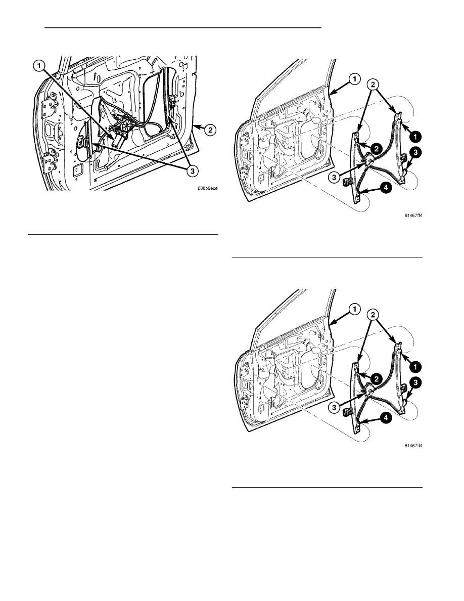
(4) Loosen screws attaching front and rear window

guide rails to inner door panel. (Fig. 28).

(5) Remove screw heads on guide rails from key

hole slots in inner door panel.

(6) Loosen screws attaching regulator to inner door

panel.

(7) Remove regulator from inner door panel.
(8) Extract rear guide rail through inner door

panel rear access hole.

(9) Extract front guide rail through front access

hole.

INSTALLATION

(1) Insert front guide rail through front access hole

(Fig. 29).

(2) Insert rear guide rail through rear access hole.
(3) Place window regulator in position on inner

door panel.

(4) Place screw heads on guide rails in position

through key hole slots in inner door panel.

(5) Tighten screws to attach front and rear guide

rails to inner door panel to 8.5 -1 0.7 N·m (75 -9 5 in.
lbs.). Tighten using the sequence in (Fig. 29).

(6) Tighten screws to attach regulator to inner

door panel to 2.8 N·m (25 in. lbs.).

(7) Install door glass. (Refer to 23 - BODY/DOOR -

FRONT/DOOR GLASS - INSTALLATION)

(8) Verify door glass alignment and operation.
(9) Install inner belt molding (Refer to 23 - BODY/

WEATHERSTRIP/SEALS/FDR

INNER

BELT

WEATHERSTRIP - INSTALLATION)

(10) Install watershield. (Refer to 23 - BODY/

DOOR - FRONT/WATERSHIELD - INSTALLATION)

Fig. 27 FRONT DOOR POWER WINDOW

1 - POWER WINDOW MOTOR
2 - FRONT DOOR
3 - GUIDE RAILS

Fig. 28 FRONT DOOR MANUAL WINDOW

1 - FRONT DOOR
2 - GUIDE RAILS
3 - MANUAL WINDOW REGULATOR

Fig. 29 FRONT DOOR MANUAL WINDOW

1 - FRONT DOOR
2 - GUIDE RAILS
3 - MANUAL WINDOW REGULATOR

RS

DOOR - FRONT

23 - 27

WINDOW REGULATOR - POWER (Continued)

DOORS - SLIDING

TABLE OF CONTENTS

page

page

CENTER HINGE

REMOVAL

. . . . . . . . . . . . . . . . . . . . . . . . . . . . . 28

INSTALLATION

. . . . . . . . . . . . . . . . . . . . . . . . . 28

SLIDING DOOR STOP BUMPER BEZEL

REMOVAL

. . . . . . . . . . . . . . . . . . . . . . . . . . . . . 29

INSTALLATION

. . . . . . . . . . . . . . . . . . . . . . . . . 29

STOP BUMPER

REMOVAL

. . . . . . . . . . . . . . . . . . . . . . . . . . . . . 29

INSTALLATION

. . . . . . . . . . . . . . . . . . . . . . . . . 29

HOLD OPEN LATCH

REMOVAL

. . . . . . . . . . . . . . . . . . . . . . . . . . . . . 29

INSTALLATION

. . . . . . . . . . . . . . . . . . . . . . . . . 29

HOLD OPEN LATCH STRIKER

REMOVAL

. . . . . . . . . . . . . . . . . . . . . . . . . . . . . 30

INSTALLATION

. . . . . . . . . . . . . . . . . . . . . . . . . 30

LATCH / LOCK ASSEMBLY

REMOVAL

. . . . . . . . . . . . . . . . . . . . . . . . . . . . . 30

INSTALLATION

. . . . . . . . . . . . . . . . . . . . . . . . . 31

INSIDE HANDLE ACTUATOR

REMOVAL

. . . . . . . . . . . . . . . . . . . . . . . . . . . . . 31

INSTALLATION

. . . . . . . . . . . . . . . . . . . . . . . . . 31

CENTER STRIKER

REMOVAL

. . . . . . . . . . . . . . . . . . . . . . . . . . . . . 32

INSTALLATION

. . . . . . . . . . . . . . . . . . . . . . . . . 32

LOWER HINGE

REMOVAL

. . . . . . . . . . . . . . . . . . . . . . . . . . . . . 32

INSTALLATION

. . . . . . . . . . . . . . . . . . . . . . . . . 32

REAR LATCH STRIKER

REMOVAL

. . . . . . . . . . . . . . . . . . . . . . . . . . . . . 33

INSTALLATION

. . . . . . . . . . . . . . . . . . . . . . . . . 33

SLIDING DOOR

REMOVAL

. . . . . . . . . . . . . . . . . . . . . . . . . . . . . 33

INSTALLATION

. . . . . . . . . . . . . . . . . . . . . . . . . 34

ADJUSTMENTS

SLIDING DOOR ADJUSTMENTS

. . . . . . . . . . 34

STABILIZER

REMOVAL

. . . . . . . . . . . . . . . . . . . . . . . . . . . . . 37

INSTALLATION

. . . . . . . . . . . . . . . . . . . . . . . . . 37

STABILIZER SOCKET

REMOVAL

. . . . . . . . . . . . . . . . . . . . . . . . . . . . . 38

INSTALLATION

. . . . . . . . . . . . . . . . . . . . . . . . . 38

TRIM PANEL

REMOVAL

. . . . . . . . . . . . . . . . . . . . . . . . . . . . . 38

INSTALLATION

. . . . . . . . . . . . . . . . . . . . . . . . . 38

INSIDE LATCH HANDLE

REMOVAL

. . . . . . . . . . . . . . . . . . . . . . . . . . . . . 38

INSTALLATION

. . . . . . . . . . . . . . . . . . . . . . . . . 39

BELLCRANK

REMOVAL

. . . . . . . . . . . . . . . . . . . . . . . . . . . . . 39

INSTALLATION

. . . . . . . . . . . . . . . . . . . . . . . . . 39

OUTSIDE HANDLE

REMOVAL

. . . . . . . . . . . . . . . . . . . . . . . . . . . . . 40

INSTALLATION

. . . . . . . . . . . . . . . . . . . . . . . . . 40

UPPER HINGE

REMOVAL

. . . . . . . . . . . . . . . . . . . . . . . . . . . . . 40

INSTALLATION

. . . . . . . . . . . . . . . . . . . . . . . . . 40

OUTSIDE HANDLE CABLE

REMOVAL

. . . . . . . . . . . . . . . . . . . . . . . . . . . . . 41

INSTALLATION

. . . . . . . . . . . . . . . . . . . . . . . . . 41

INSIDE HANDLE CABLE

REMOVAL

. . . . . . . . . . . . . . . . . . . . . . . . . . . . . 42

INSTALLATION

. . . . . . . . . . . . . . . . . . . . . . . . . 42

HOLD OPEN LATCH CABLE

REMOVAL

. . . . . . . . . . . . . . . . . . . . . . . . . . . . . 43

INSTALLATION

. . . . . . . . . . . . . . . . . . . . . . . . . 43

CENTER HINGE

REMOVAL

NOTE: For power sliding door procedures refer to
POWER SLIDING DOOR SYSTEM in the ELECTRI-
CAL section.

(1) Open sliding door to the mid point of its travel.
(2) Support sliding door on a suitable lifting

device.

(3) Mark outline of center hinge of inner door

panel to aid installation.

(4) Remove bolts attaching center hinge to sliding

door.

(5) Remove center hinge from sliding door.
(6) Roll center hinge to rear of roller channel.
(7) Remove center hinge from vehicle.

INSTALLATION

NOTE: For power sliding door procedures refer to
POWER SLIDING DOOR SYSTEM in the ELECTRI-
CAL section.

23 - 28

DOORS - SLIDING

RS

NOTE: Center hinge has an adjustable bolt for
up/down alignment. (Refer to 23 - BODY/DOORS -
SLIDING/SLIDING DOOR - ADJUSTMENTS)

(1) Place center hinge in position on vehicle.
(2) Roll center hinge forward in roller channel.
(3) Place center hinge in position on sliding door

and align marks.

(4) Install bolts attaching center hinge to sliding

door.

(5) Verify sliding door alignment and operation.

SLIDING DOOR STOP BUMPER
BEZEL

REMOVAL

(1) Using a trim stick (C-4755), disengage clips

attaching door stop bumper bezel to the door trim
panel.

(2) Remove bezel from vehicle (Fig. 1).

INSTALLATION

(1) Place door stop bumper bezel into position (Fig.

1).

(2) Engage clips attaching door stop bumper bezel

to the door trim panel.

STOP BUMPER

REMOVAL

(1) Remove door stop bumper bezel.
(2) Loosen screws attaching rear of stop bumper to

door inner panel (Fig. 1).

(3) Remove screw attaching front of door stop

bumper to door inner panel.

(4) Remove door stop bumper from vehicle.

INSTALLATION

(1) Place stop bumper in position on vehicle.
(2) Install screw attaching front of stop bumper to

door inner panel (Fig. 1).

(3) Tighten screws attaching rear of stop bumper

to door inner panel.

(4) Install door stop bumper bezel.

HOLD OPEN LATCH

REMOVAL

(1) Open sliding door.
(2) Remove sliding door sill plate. (Refer to 23 -

BODY/INTERIOR/SLIDING DOOR SILL PLATE -
REMOVAL)

(3) Remove nuts attaching hold open latch to lower

roller arm (Fig. 2).

(4) Remove hold open latch from lower arm.
(5) Disconnect cable from hold open latch.
(6) Remove hold open latch from vehicle.

INSTALLATION

(1) Place hold open latch in position on vehicle.
(2) Connect cable to hold open latch.
(3) Place hold open latch in position on lower arm.
(4) Install nuts attaching the hold open latch to

lower roller arm. Tighten nuts to 5 N·m (45 in. lbs.)
torque.

(5) Install sliding door sill plate. (Refer to 23 -

BODY/INTERIOR/SLIDING DOOR SILL PLATE -
INSTALLATION)

(6) Verify sliding door operation.

Fig. 1 SLIDING DOOR STOP BUMPER

1 - DOOR STOP BUMPER
2 - DOOR STOP BUMPER BEZEL
3 - SLIDING DOOR

Fig. 2 SLIDING DOOR HOLD OPEN LATCH

1 - SLIDING DOOR HOLD OPEN LATCH - MANUAL DOOR
2 - LOWER ROLLER ARM

RS

DOORS - SLIDING

23 - 29

CENTER HINGE (Continued)

HOLD OPEN LATCH STRIKER

REMOVAL

NOTE: For power sliding door procedures refer to
POWER SLIDING DOOR SYSTEM in the ELECTRI-
CAL section.

(1) Open sliding door, do not latch open.
(2) Remove sliding door sill plate. (Refer to 23 -

BODY/INTERIOR/SLIDING DOOR SILL PLATE -
REMOVAL)

(3) Remove two bolts attaching sliding door hold

open latch striker to door sill (Fig. 3).

(4) Remove hold open latch striker from vehicle.

INSTALLATION

NOTE: For power sliding door procedures refer to
POWER SLIDING DOOR SYSTEM in the ELECTRI-
CAL section.

(1) Place hold open latch striker in position on

vehicle.

(2) Install two bolts attaching sliding door hold

open latch striker to door sill.

(3) Install sliding door sill plate. (Refer to 23 -

BODY/INTERIOR/SLIDING DOOR SILL PLATE -
INSTALLATION)

(4) Verify sliding door operation.

LATCH / LOCK ASSEMBLY

REMOVAL

NOTE: For power sliding door procedures refer to
POWER SLIDING DOOR SYSTEM in the ELECTRI-
CAL section.

(1) Remove sliding door trim panel. (Refer to 23 -

BODY/DOORS

-

SLIDING/TRIM

PANEL

-

REMOVAL)

(2) Remove sliding door stop bumper. (Refer to 23 -

BODY/DOORS

-

SLIDING/STOP

BUMPER

-

REMOVAL)

(3) Peel watershield away from adhesive around

perimeter of inner door panel.

(4) Disengage

external

cable

from

latch/lock

assembly (Fig. 4).

(5) Remove foam block.
(6) Remove inside door handle assembly (Refer to

23 - BODY/DOORS - SLIDING/INSIDE LATCH
HANDLE - REMOVAL).

(7) Disengage inside cable from latch/lock assem-

bly.

(8) Disengage link from bellcrank.
(9) Disengage hold open latch cable from lower

hinge.

(10) Remove bolts attaching latch/lock control to

sliding door (Fig. 5).

(11) If equipped, lower latch and disconnect wire

connector from power door lock motor.

(12) Remove latch/lock from door.

Fig. 3 SLIDING DOOR HOLD OPEN LATCH STRIKER

1 - POWER DOOR LOWER TRACK
2 - POWER DOOR HOLDING STRIKER
3 - MANUAL DOOR HOLDING STRIKER
4 - MANUAL DOOR LOWER TRACK

Fig. 4 SLIDING DOOR LATCH/LOCK ASSEMBLY

1 - SLIDING DOOR
2 - LATCH LOCK ASSEMBLY

23 - 30

DOORS - SLIDING

RS


Content   ..  1110  1111  1112  1113   ..