Chrysler RG Voyager. Manual - part 1111


  Index      Chrysler     Chrysler RG Voyager - service repair manual 2005 year


Search            


Content   ..  1109  1110  1111  1112   ..


Chrysler RG Voyager. Manual - part 1111


(4) Tighten fasteners to 28 N·m (21 ft. lbs.) torque.
(5) Verify door fit and operation. Adjust latch

striker as necessary.

LOCK CYLINDER

REMOVAL

(1) Roll door glass up.
(2) Remove front door watershield as necessary to

gain access to the outside door handle. (Refer to 23 -
BODY/DOOR

-

FRONT/WATERSHIELD

-

REMOVAL)

(3) Through access hole at rear of inner door

panel, disconnect Vehicle Theft Security System
(VTSS)

switch

connector

from

door

harness,

if

equipped.

(4) Disengage push in fasteners attaching VTSS

switch harness to inner door reinforcement bar, if
equipped.

(5) Disengage clip holding door latch linkage to

door latch (Fig. 21).

(6) Remove latch linkage from latch.
(7) Disengage clip holding door lock linkage to

door latch.

(8) Remove lock linkage from latch.
(9) Remove nuts attaching outside door handle to

door outer panel.

(10) Remove outside door handle from vehicle.
(11) Disengage clip holding lock cylinder into out-

side handle.

(12) Pull lock cylinder from door handle.

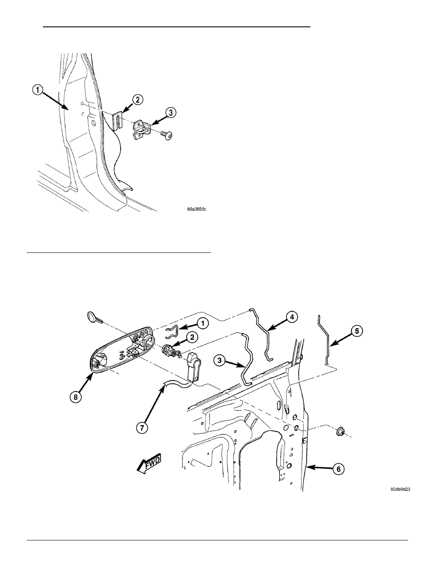
Fig. 21 OUTSIDE DOOR HANDLE

1 - CLIP
2 - LOCK CYLINDER
3 - KEY CYLINDER TO LATCH LINK
4 - OUTSIDE HANDLE TO LATCH LINK

5 - LOCK KNOB LINK
6 - FRONT DOOR
7 - KEY POSITION SWITCH
8 - OUTSIDE HANDLE

Fig. 20 DOOR LATCH STRIKER

1 - B-PILLAR
2 - SHIM
3 - DOOR LATCH STRIKER

RS

DOOR - FRONT

23 - 23

LATCH STRIKER (Continued)

INSTALLATION

(1) Engage clip into outside handle to hold lock

cylinder (Fig. 21).

(2) With link arm toward rear of vehicle, push lock

cylinder into door handle until clip snaps into place.

(3) Insert lock linkage into door latch.
(4) Engage clip to hold door lock linkage to latch.
(5) Insert latch linkage into door latch.
(6) Engage clip to hold door latch linkage to latch.
(7) Install

push

in

fasteners

attaching

VTSS

switch harness to inner door reinforcement bar, if
equipped.

(8) Connect VTSS switch connector into door har-

ness, if equipped.

(9) Verify door latch operation.
(10) Install watershield and door trim panel.

TRIM PANEL

REMOVAL

(1) Remove the plug and remove screw attaching

door pull cup to inner door panel.

(2) Remove switch bezel and disconnect power win-

dow/memory switch.

(3) Remove screws attaching trim panel to door

from below map pocket.

(4) If equipped, remove window crank. (Refer to 23

-

BODY/DOOR

-

FRONT/WINDOW

CRANK

-

REMOVAL)

(5) Remove screw holding door trim to door panel

from behind inside latch release handle.

(6) Disengage clips attaching door trim to door

frame around perimeter of panel.

(7) Lift trim panel upward to disengage flange

from inner belt molding at top of door.

(8) Tilt top of trim panel away from door to gain

access to latch linkage.

(9) Disengage clip attaching linkage rod to inside

latch release handle (Fig. 22).

(10) Separate linkage rod from latch handle.
(11) Disconnect the power door switch, courtesy

lamp electrical connectors.

(12) Remove front door trim panel from vehicle.

INSTALLATION

(1) Hold top of trim panel away from door to gain

access to latch linkage.

(2) Place linkage rod in position on latch handle.
(3) Engage clip to hold linkage rod to inside latch

release handle.

(4) Place front door trim panel in position on door.
(5) Install trim panel into inner belt molding at

top of door.

(6) Install clips to attach door trim to door frame

around perimeter of panel.

(7) If equipped, install screw to attach door trim to

door panel behind inside latch release handle.

(8) If equipped, connect power switch into wire

connector.

(9) Place power accessary switch in position on

door trim.

(10) Connect wire connector into memory seat/mir-

ror switch and install switch into trim panel.

(11) Install screws to attach accessary switch

panel to door trim.

(12) Install screw cover into switch panel.
(13) If equipped, install window crank.
(14) If equipped, install screws to attach trim

panel to door inside map pocket.

(15) If equipped, install screw to attach door pull

cup to inner door panel.

(16) If equipped, install screws to attach door

assist handle to inner door panel.

(17) Connect wire connector into courtesy lamp.
(18) Install lamp in door trim.
(19) Install switch bezel.

WATERSHIELD

REMOVAL

(1) Remove door trim panel. (Refer to 23 - BODY/

DOOR - FRONT/TRIM PANEL - REMOVAL)

(2) Remove the front door speaker. (Refer to 8 -

ELECTRICAL/AUDIO/SPEAKER - REMOVAL)

(3) Peel watershield away from adhesive around

perimeter of inner door panel.

Fig. 22 INSIDE DOOR HANDLE LINKAGE

1 - DOOR LATCH HANDLE
2 - DOOR TRIM
3 - LATCH LINKAGE
4 - CLIP
5 - MEMORY SEAT SWITCH

23 - 24

DOOR - FRONT

RS

LOCK CYLINDER (Continued)

INSTALLATION

(1) Insure

that

enough

adhesive

remains

to

securely retain the water dam. Replace as necessary.

(2) Place

the

shield

into

position

and

press

securely to adhesive making sure to properly route
wiring and linkages.

(3) Install the front door speaker. (Refer to 8 -

ELECTRICAL/AUDIO/SPEAKER - INSTALLATION)

(4) Install door trim panel. (Refer to 23 - BODY/

DOOR - FRONT/TRIM PANEL - INSTALLATION)

WINDOW CRANK

REMOVAL

(1) Using a window crank removal tool, disengage

clip attaching window crank to regulator shaft (Fig.
23).

NOTE: Wrap a shop towel around the window crank
to catch the clip when it springs out.

(2) Pull window crank from regulator shaft.

INSTALLATION

(1) Place the clip on to the window crank handle.
(2) Position window crank to regulator shaft.
(3) Push window crank onto regulator shaft to

engage retaining clip.

EXTERIOR HANDLE

REMOVAL

(1) Roll door glass up.
(2) Remove the watershield as necessary to gain

access to the outside door handle. (Refer to 23 -

BODY/DOOR

-

FRONT/WATERSHIELD

-

REMOVAL)

(3) Through access hole at rear of inner door

panel, disconnect Vehicle Theft Security System
(VTSS)

switch

connector

from

door

harness,

if

equipped.

(4) Disengage push in fasteners attaching VTSS

switch harness to inner door reinforcement bar, if
equipped.

(5) Disengage clip holding door latch linkage to

door latch (Fig. 21).

(6) Remove latch linkage from latch.
(7) Disengage clip holding door lock linkage to

door latch.

(8) Remove lock linkage from latch.
(9) Remove nuts holding outside door handle to

door outer panel.

(10) Remove outside door handle from vehicle.

INSTALLATION

If outside door handle replacement is necessary,

transfer lock cylinder from the original handle to the
new one.

(1) Place outside door handle in position on vehi-

cle.

(2) Install nuts attaching outside door handle to

door outer panel (Fig. 21). Tighten nuts to 6 N·m (50
in. lbs.).

(3) Insert lock linkage into door latch.
(4) Engage clip to hold door lock linkage to latch.
(5) Insert latch linkage into door latch.
(6) Engage clip to hold door latch linkage to latch.
(7) Install push-in fasteners to hold VTSS switch

harness to inner door reinforcement bar, if equipped.

(8) Connect VTSS switch connector into door har-

ness, if equipped.

(9) Verify door latch operation.
(10) Install sound shield and door trim panel.

WINDOW REGULATOR -
POWER

REMOVAL

(1) Remove watershield. (Refer to 23 - BODY/

DOOR - FRONT/WATERSHIELD - REMOVAL)

(2) Remove inner belt molding. (Refer to 23 -

BODY/WEATHERSTRIP/SEALS/FDR INNER BELT
WEATHERSTRIP - REMOVAL)

(3) Remove door glass. (Refer to 23 - BODY/DOOR

- FRONT/DOOR GLASS - REMOVAL).

(4) Disconnect wire connector from power window

motor.

(5) Loosen screws attaching front and rear window

guide rails to inner door panel (Fig. 24).

Fig. 23 WINDOW CRANK - TYPICAL

1 - WINDOW CRANK REMOVAL TOOL
2 - WINDOW CRANK

RS

DOOR - FRONT

23 - 25

WATERSHIELD (Continued)

(6) Remove screw heads on guide rails from key

hole slots in inner door panel.

(7) Loosen screws attaching motor/housing to inner

door panel.

(8) Remove regulator from inner door panel (Fig.

25).

(9) Extract rear guide rail through inner door

panel rear access hole (Fig. 25).

(10) Extract front guide rail through front access

hole.

INSTALLATION

(1) Insert front guide rail through front access hole

(Fig. 26).

(2) Insert rear guide rail through rear access hole.
(3) Place window regulator in position on inner

door panel.

(4) Place screw heads on guide rails in position

through key hole slots in inner door panel.

(5) Tighten screws to attach front and rear guide

rails to inner door panel to 8.5 - 10.7 N·m (75 - 95 in.
lbs.). Tighten using the sequence in (Fig. 26).

(6) Tighten screws to attach motor/housing to

inner door panel to 2.8 N·m (25 in. lbs.) (Fig. 27).

(7) Connect wire connector into power window

motor.

(8) Install door glass. (Refer to 23 - BODY/DOOR -

FRONT/DOOR GLASS - INSTALLATION)

(9) Verify door glass alignment and operation.
(10) Install inner belt molding (Refer to 23 -

BODY/WEATHERSTRIP/SEALS/FDR INNER BELT
WEATHERSTRIP - INSTALLATION)

(11) Install watershield. (Refer to 23 - BODY/

DOOR - FRONT/WATERSHIELD - INSTALLATION)

Fig. 24 FRONT DOOR POWER WINDOW

1 - POWER WINDOW MOTOR
2 - FRONT DOOR
3 - GUIDE RAILS

Fig. 25 FRONT DOOR POWER WINDOW

1 - FRONT DOOR
2 - GUIDE RAILS
3 - POWER WINDOW MOTOR

Fig. 26 FRONT DOOR POWER WINDOW

1 - FRONT DOOR
2 - GUIDE RAILS
3 - POWER WINDOW MOTOR

23 - 26

DOOR - FRONT

RS

WINDOW REGULATOR - POWER (Continued)


Content   ..  1109  1110  1111  1112   ..