Content .. 1101 1102 1103 1104 ..
Chrysler RG Voyager. Manual - part 1103
original style valve stem cap is securely installed to
keep moisture out of sensor.
(7) Install wheel and tire assembly on vehicle.
(Refer to 22 - TIRES/WHEELS - INSTALLATION)
(8) Drive vehicle for a minimum of five minutes
while maintaining a continuous speed above 15 mph
(24 km/h). During this time the system will learn the
new sensor ID code and will clear any DTC’s auto-
matically.
NOTE: If a sensor cannot be trained, refer to appro-
priate diagnostic information.
TIRES
DESCRIPTION
DESCRIPTION - TIRE
Tires are designed and engineered for each specific
vehicle. They provide the best overall performance
for normal operation. The ride and handling charac-
teristics match the vehicle’s requirements. With
proper care they will give excellent reliability, trac-
tion, skid resistance, and tread life.
Driving habits have more effect on tire life than
any other factor. Careful drivers will obtain, in most
cases, much greater mileage than severe use or care-
less drivers. A few of the driving habits which will
shorten the life of any tire are:
• Rapid acceleration
• Severe application of brakes
• High-speed driving
• Taking turns at excessive speeds
• Striking curbs and other obstacles
• Operating vehicle with over or under inflated
tire pressures
Radial ply tires are more prone to irregular tread
wear. It is important to follow the tire rotation inter-
val shown in the section on Tire Rotation. This will
help to achieve a greater tread-life potential.
TIRE IDENTIFICATION
Tire type, size, load index and speed rating are
encoded in the letters and numbers imprinted on the
side wall of the tire. Refer to the Tire Identification
chart to decipher the code. For example purposes, the
tire size P225/60 R 16 97 T is used in the chart. An
All Season type tire will also have either M + S, M &
S or M - S (indicating mud and snow traction)
imprinted on the side wall. An Extra or Light Load
marking “XL” or “LL” may also be listed on the side-
wall. The absence of an “XL” or “LL” marking infers
a standard load tire.
TIRE IDENTIFICATION
P
TIRE TYPE (Not
present on all tires)
P - Passenger
T - Temporary
C - Commercial
LT - Light Truck
225
SECTIONAL WIDTH
SHOWN IN
MILLIMETERS
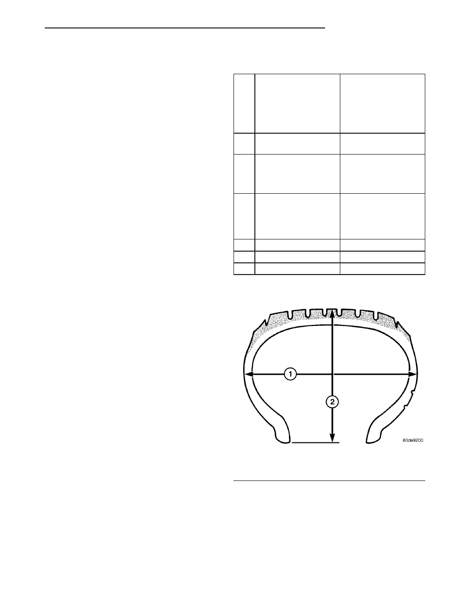
60
ASPECT RATIO
SECTIONAL HEIGHT
÷ SECTIONAL WIDTH
(Refer to Aspect Ratio
Figure 28 )
R
CONSTRUCTION
TYPE
R - RADIAL
B - BIAS BELTED
D - DIAGONAL (BIAS)
16
WHEEL DIAMETER
SHOWN IN INCHES
97
LOAD INDEX
*
T
SPEED RATING
*
* NOTE: Consult the tire manufacturer regarding
any questions on tire specifications or capabilities.
TIRE CHAINS
Refer to the owners manual supplied with the vehi-
cle to determine whether the use of tire chains is per-
mitted on this vehicle.
Fig. 28 Tire Aspect Ratio
1 - SECTIONAL WIDTH
2 - SECTIONAL HEIGHT
RS
TIRES/WHEELS
22 - 15
SENSOR - TPM (Continued)