Chrysler RG Voyager. Manual - part 1101


  Index      Chrysler     Chrysler RG Voyager - service repair manual 2005 year


Search            


Content   ..  1099  1100  1101  1102   ..


Chrysler RG Voyager. Manual - part 1101


The aluminum wheels on this vehicle use a unique

wheel weight (Fig. 10). This wheel weight is designed
to fit the contoured surface of the wheel (Fig. 10).
When balancing an aluminum wheel, this wheel
weight must be used. Do not use any other type of
wheel weight. It will not properly fit the contour of
the wheel.

Always verify the Balance. When using off-vehicle

equipment, rotate assembly 180 degrees on balance
equipment to verify balance. Variation should not be
more than 0.125 (

1

8

) ounce. If variation is more than

0.125 ounce, balancing equipment could be malfunc-
tioning.

If difficult to balance, break down the wheel and

tire assembly and check for loose debris inside tire.
Prior to disassembly, mark (index) the tire at the
valve stem. Use this mark in order to remount the
tire in its original orientation with respect to the
wheel.

STANDARD PROCEDURE - TIRE AND WHEEL
MATCH MOUNTING

Wheels and tires are match mounted at the factory.

This means that the high spot of the tire is matched
to the low spot on the wheel rim. This technique is
used to reduce runout in the wheel and tire assem-
bly. The high spot on the tire is marked with a paint
mark or a bright colored adhesive label on the out-
board sidewall. The low spot on the wheel is identi-
fied with a label on the outside of the rim and a dot
or line in the drop well area of the rim (inside where
the tire mounts). If the outside label has been
removed, the tire will have to be removed to locate
the dot or line on the inside of the rim. The tire can
then be match mounted to the tire.

Information on match mounting the tire to the

wheel can be found in Tire and Wheel Runout/Match
Mounting, items (2) through (5), within Diagnosis
And Testing - Tire And Wheel Vibration. (Refer to 22
- TIRES/WHEELS - DIAGNOSIS AND TESTING)

STANDARD PROCEDURE - TIRE AND WHEEL
ROTATION

NON-DIRECTIONAL TREAD PATTERN TIRES

Tires on the front and rear axles operate at differ-

ent loads and perform different functions. For these
reasons, they wear at unequal rates, and tend to
develop irregular wear patterns. These effects can be
reduced by timely rotation of tires. The benefits of
rotation are especially worthwhile. Rotation will
increase tread life, help to maintain mud, snow, and
wet traction levels, and contribute to a smooth, quiet
ride.

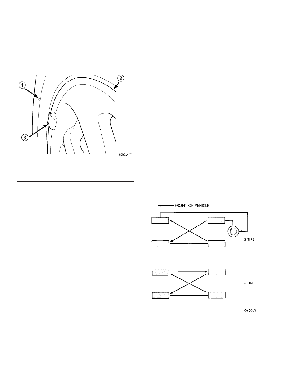
The suggested rotation method is the forward-cross

tire rotation method (Fig. 11). This method takes
advantage of current tire industry practice which
allows rotation of radial-ply tires. Other rotation
methods may be used, but may not have all the ben-
efits of the recommended method.

NOTE: Only the 4 tire rotation method may be used
if the vehicle is equipped with a low mileage or tem-
porary spare tire.

DIRECTIONAL TREAD PATTERN TIRES

Some vehicles are fitted with special high-perfor-

mance tires having a directional tread pattern. These
tires are designed to improve traction on wet pave-

Fig. 10 Aluminum Wheel Weight

1 - TIRE
2 - WHEEL
3 - WHEEL WEIGHT

Fig. 11 Forward-Cross Tire Rotation Method

RS

TIRES/WHEELS

22 - 7

TIRES/WHEELS (Continued)

ment. To obtain the full benefits of this design, the
tires must be installed so that they rotate in the cor-
rect direction. This is indicated by arrows on the tire
sidewalls.

When wheels and tires are being installed, extra

care is needed to ensure that this direction of rota-
tion is maintained.

Refer to Owner’s Manual for rotation schedule.

REMOVAL

REMOVAL - TIRE AND WHEEL ASSEMBLY
(ALUMINUM WHEEL)

(1) Raise the vehicle so the tire and wheel assem-

bly clears ground level.

(2) Remove the 5 wheel mounting nuts from the

studs.

(3) Remove the tire and wheel from the hub.

REMOVAL - TIRE AND WHEEL ASSEMBLY
(STEEL WHEEL)

(1) Raise the vehicle so the tire and wheel assem-

bly clears ground level.

(2) Noting the location of the valve stem in rela-

tionship to the wheel mounting nuts, remove the
three wheel mounting nuts securing the wheel cover
to the wheel and hub (Fig. 12).

CAUTION: When removing the wheel cover, do not
pry the wheel cover from the wheel. This can result
in damage to the wheel cover. The wheel cover is
removed by pulling it off the wheel by hand.

(3) Grasp the wheel cover at the edges in line with

the remaining installed wheel mounting nuts and

pull straight outward from the wheel. This will pop
the wheel cover retaining tabs over the two remain-
ing wheel nuts, removing the wheel cover from the
vehicle.

(4) Remove the two remaining wheel mounting

nuts from the hub’s studs.

(5) Remove the wheel and tire from the hub.

INSTALLATION

INSTALLATION - TIRE AND WHEEL ASSEMBLY
(ALUMINUM WHEEL)

NOTE: Never use oil or grease on studs or wheel
mounting nuts.

(1) Position the tire and wheel assembly on the

wheel mounting studs using the hub pilot as a guide.
Place and hold the wheel flush up against the mount-
ing surface.

(2) Loosely install all 5 wheel mounting nuts.

Lightly snug the wheel nuts, then progressively
tighten them in the proper sequence (Fig. 13).
Tighten wheel mounting nuts to 135 N·m (100 ft.
lbs.).

(3) Lower the vehicle.

INSTALLATION - TIRE AND WHEEL ASSEMBLY
(STEEL WHEEL)

NOTE: Never use oil or grease on studs or wheel
mounting nuts.

(1) Position the tire and wheel assembly on the

wheel mounting studs using the hub pilot as a guide.
Place and hold the wheel flush up against the mount-
ing surface.

Fig. 12 NUTS SECURING WHEEL COVER

1 - VALVE STEM
2 - BOLT-ON WHEEL COVER
3 - NUTS SECURING WHEEL COVER

Fig. 13 Tightening Sequence

22 - 8

TIRES/WHEELS

RS

TIRES/WHEELS (Continued)

NOTE: Wheel mounting nuts must be installed on
the studs as shown (Fig. 14) to allow proper instal-
lation of the wheel cover.

(2) Using the valve stem as an index placed at the

12 O’clock position, install and lightly tighten two
wheel mounting nuts on the studs located at the 4
O’clock and 8 O’clock positions as shown (Fig. 14).

(3) Place the wheel cover on the wheel in the fol-

lowing fashion:

(a) Align the valve notch in the wheel cover with

the valve stem on the wheel.

(b) At the same time, align the two holes in the

wheel cover having the retaining tabs with the two
installed wheel nuts (Fig. 15).

(c) Press in on center of wheel cover until wheel

cover retaining tabs push past and engage rear of
previously installed wheel mounting nuts (Fig. 15).
This will hold the wheel cover in place.
(4) Install and lightly tighten the three remain-

ing wheel mounting nuts, securing the wheel cover in
place (Fig. 12).

(5) Progressively tighten all five wheel mounting

nuts in the proper sequence (Fig. 16). Tighten wheel
nuts to a torque of 135 N·m (100 ft. lbs.).

(6) Lower the vehicle.

TIRE PRESSURE MONITORING

DESCRIPTION

The Tire Pressure Monitoring (TPM) system moni-

tors air pressure in the four road tires. Pressure in
the spare tire is not monitored.

The system alerts the driver when tire pressure

falls outside predetermined thresholds. (Refer to 22 -
TIRES/WHEELS/TIRE PRESSURE MONITORING -
OPERATION)

There is a sensor (transmitter) located in each of

the vehicle’s four road wheels that operates on a 315
MHz radio frequency (Fig. 17).

The TPM system is controlled by the Sentry Key

Remote Entry Module (SKREEM). When Diagnosing
the TPM, use a scan tool accessing the SKREEM.

An indicator lamp located in the instrument clus-

ter and the Electronic Vehicle Information Center
(EVIC) are used to communicate system information.

For further information, refer to the Owners Man-

ual or the appropriate diagnostic information.

Fig. 14 TWO WHEEL MOUNTING NUTS INSTALLED

1 - WHEEL
2 - VALVE STEM
3 - HUB PILOT
4 - NUTS

Fig. 15 WHEEL COVER INSTALLATION OVER TWO

NUTS

1 - RETAINING TABS
2 - VALVE STEM
3 - BOLT-ON WHEEL COVER

Fig. 16 NUT TIGHTENING SEQUENCE

RS

TIRES/WHEELS

22 - 9

TIRES/WHEELS (Continued)

OPERATION

The Tire Pressure Monitoring (TPM) system uses

radio and sensor technology to monitor tire air pres-
sure levels. Sensors, mounted to each road wheel as
part of the valve stem, transmit an RF signal indi-
cating their individual pressure to a receiver located
in the Sentry Key Remote Entry Module (SKREEM).
These transmissions occur approximately once every
minute at speeds over 15 mph (24 km/h). The Tire
Pressure Monitoring system remains active even if
no tire pressure related message is displayed.

The sensors lay dormant (Park Mode), then wake

and start transmitting (Drive Mode) when the vehicle
first reaches speeds over 15 mph (24 km/h). Once the
wheels stop rotating for a period of approximately 20
minutes, the sensors shut down until again awaken.
Although not transmitting as when in Drive Mode,
while in Park Mode, the sensors still transmit
approximately once every 13 hours to let the receiver
know air pressure status at that time.

If the system detects that the tire pressure in any

road tire is going low, beyond the Low Pressure
(lamp) ON threshold (see following table), the TPM
system will display a message in the instrument
cluster and continuously illuminate an indicator
lamp. This message will be displayed for the rest of
the ignition cycle, or until the Low Tire pressure con-
dition has been corrected. Once pressure in the sus-
pect tire raises above the Low Pressure (lamp) OFF
Threshold, the lamp will go out and the system
returns to normal within approximately two minutes
time. If the C/T, MENU, STEP or RESET button is
pressed, the message is replaced by the new message

requested; however, if the Low Tire condition has not
been corrected, the Low Tire pressure message will
again be displayed.

If a system fault is detected, the indicator lamp

will flash on/off for 10 seconds, once every 10 min-
utes.

For further information, refer to the Owners Man-

ual or the Appropriate Diagnostic Information.

TPM THRESHOLD PRESSURES

DESCRIPTION

SPECIFICATION

High Pressure ON Threshold

48 PSI (331 kPa)

High Pressure OFF Threshold

43 PSI (296 kPa)

Placard Pressure (Cold)

36 PSI (248 kPa)

Low Pressure OFF Threshold

33 PSI (214 kPa)

Low Pressure ON Threshold

28 PSI (193 kPa)

SENSOR - TPM

DESCRIPTION

On vehicles equipped with Tire Pressure Monitor-

ing (TPM), one tire pressure sensor is mounted to
each wheel in place of the traditional tire valve stem
(Fig. 18). Each sensor has an internal battery that
lasts up to 10 years. The battery is not serviceable.
At the time of battery failure, the sensor must be
replaced.

The TPM system operates on a 315 MHz radio fre-

quency (Fig. 18).

Fig. 17 Tire Pressure Sensor

1 - ANTENNA STRAP
2 - VALVE STEM

Fig. 18 Tire Pressure Sensor

1 - ANTENNA STRAP
2 - VALVE STEM

22 - 10

TIRES/WHEELS

RS

TIRE PRESSURE MONITORING (Continued)


Content   ..  1099  1100  1101  1102   ..