Chrysler RG Voyager. Manual - part 1047


  Index      Chrysler     Chrysler RG Voyager - service repair manual 2005 year


Search            


Content   ..  1045  1046  1047  1048   ..


Chrysler RG Voyager. Manual - part 1047


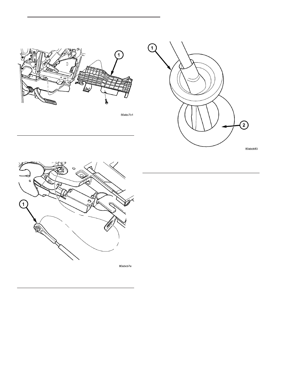
(9) Disconnect gear shift cable from gear shift

lever (Fig. 213).

(10) Remove gear shift cable from column bracket

(Fig. 213).

(11) Disengage grommet from dash panel (Fig.

214) and remove gear shift cable from inside vehicle.

HOLDING CLUTCHES

DESCRIPTION

Two hydraulically applied multi-disc clutches are

used to hold planetary geartrain components station-
ary while the input clutches drive others. The 2/4
and Low/Reverse clutches are considered holding
clutches and are contained at the rear of the trans-
axle case. (Fig. 215).

OPERATION

NOTE: Refer to the “Elements In Use” chart in Diag-
nosis and Testing for a collective view of which
clutch elements are applied at each position of the
selector lever.

2/4 CLUTCH

The 2/4 clutch is hydraulically applied in second

and fourth gears by pressurized fluid against the 2/4
clutch piston. When the 2/4 clutch is applied, the
front sun gear assembly is held or grounded to the
transaxle case.

LOW/REVERSE CLUTCH

The Low/Reverse clutch is hydraulically applied in

park, reverse, neutral, and first gears by pressurized
fluid against the Low/Reverse clutch piston. When
the Low/Reverse clutch is applied, the front planet

Fig. 212 Knee Bolster

1 - KNEE BOLSTER

Fig. 213 Gearshift Cable at Column

1 - GEAR SHIFT CABLE

Fig. 214 Gearshift Cable/Grommet at Dash Panel

1 - CABLE GROMMET
2 - DASH PANEL

RS

40TE AUTOMATIC TRANSAXLE

21 - 209

GEAR SHIFT CABLE (Continued)

carrier/rear annulus assembly is held or grounded to
the transaxle case.

INPUT CLUTCH ASSEMBLY

DISASSEMBLY

(1) Mount input clutch assembly to Input Clutch

Pressure Fixture (Tool 8391).

(2) Tap down reverse clutch reaction plate to

release pressure from snap ring (Fig. 216).

(3) Remove reverse clutch snap ring (Fig. 217).

Fig. 215 2/4 and Low/Reverse Clutches

1 - FRONT PLANET CARRIER/REAR ANNULUS
2 - 2/4 CLUTCH
3 - LOW/REVERSE CLUTCH
4 - REAR PLANET CARRIER/FRONT ANNULUS
5 - REAR SUN GEAR
6 - FRONT SUN GEAR ASSEMBLY

Fig. 216 Tapping Reaction Plate

1 - #4 THRUST PLATE (SELECT)
2 - TAP DOWN REVERSE CLUTCH REACTION PLATE TO
REMOVE OR INSTALL SNAP RING
3 - INPUT SHAFT CLUTCHES RETAINER ASSEMBLY
4 - REVERSE CLUTCH REACTION PLATE

Fig. 217 Reverse Clutch Snap Ring

1 - REACTION PLATE
2 - SCREWDRIVER
3 - REVERSE CLUTCH SNAP RING (SELECT)

21 - 210

40TE AUTOMATIC TRANSAXLE

RS

HOLDING CLUTCHES (Continued)

(4) Pry up and remove reverse clutch reaction

plate (Fig. 218).

(5) Remove reverse clutch pack (Fig. 219). Tag

components for assembly identification.

Fig. 218 Pry Reverse Clutch Reaction Plate

1 - REVERSE CLUTCH REACTION PLATE
2 - SCREWDRIVER
3 - SCREWDRIVER

Fig. 219 Reverse Clutch Assembly

1 - SNAP RING
2 - REACTION PLATE
3 - CLUTCH DISC (2)

4 - CLUTCH PLATE (1)
5 - INPUT CLUTCH ASSEMBLY

RS

40TE AUTOMATIC TRANSAXLE

21 - 211

INPUT CLUTCH ASSEMBLY (Continued)

(6) Remove the OD/Reverse pressure plate snap

ring (Fig. 220).

(7) Remove OD/Reverse pressure plate (Fig. 220).
(8) Remove OD/Reverse pressure plate wave snap

ring (Fig. 220).

(9) Remove OD clutch pack (Fig. 220). Tag com-

ponents for assembly identification.

Fig. 220 Overdrive Clutch Assembly

1 - SNAP RING
2 - OD/REVERSE PRESSURE PLATE
3 - SNAP RING (WAVE)

4 - CLUTCH DISC (3)
5 - CLUTCH STEEL (2)
6 - INPUT CLUTCH ASSEMBLY

21 - 212

40TE AUTOMATIC TRANSAXLE

RS

INPUT CLUTCH ASSEMBLY (Continued)


Content   ..  1045  1046  1047  1048   ..