Chrysler Pacifica. Manual - part 828


  Index      Chrysler     Chrysler Pacifica - service repair manual 2005 year


Search            


Content   ..  826  827  828  829   ..


Chrysler Pacifica. Manual - part 828


OUTSIDE HANDLE

REMOVAL

(1) Remove liftgate trim panel. (Refer to 23 -

BODY/DECKLID/HATCH/LIFTGATE/TAILGATE/
TRIM PANEL - REMOVAL).

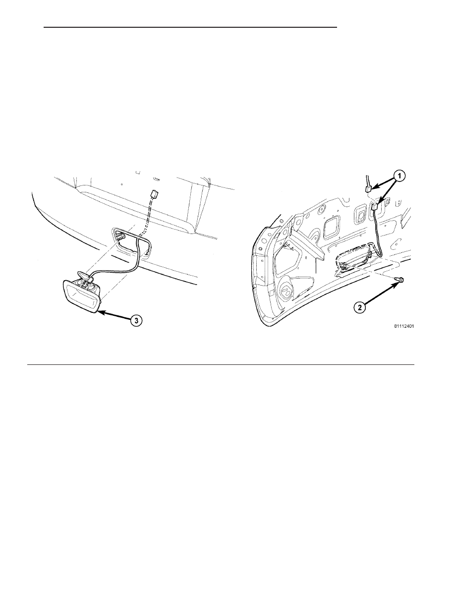
(2) Disconnect the exterior handle electrical con-

nectors (Fig. 1).

(3) Remove the two screws attaching liftgate han-

dle to liftgate inner panel.

(4) Remove the exterior handle/license plate light

assembly.

INSTALLATION

(1) Route the exterior handle electrical connector

through the door and position handle (Fig. 1).

(2) Install the two out screws liftgate handle to

liftgate inner panel. Tighten screws to 8 N·m (80 in.
lbs.).

(3) Connect the electrical connector.
(4) Install the trim panel. (Refer to 23 - BODY/

TAILGATE/TRIM PANEL - INSTALLATION).

Fig. 1 OUTSIDE HANDLE

1 - WIRE HARNESS
2 - ATTACHING SCREWS

3 - OUTSIDE HANDLE ASSEMBLY

CS

LIFTGATE

23 - 107

HINGE

REMOVAL

(1) Release liftgate latch and open liftgate.
(2) Support liftgate on a suitable lifting device in

the full open position.

(3) Using a grease pencil or equivalent, mark the

hinge location.

(4) Remove liftgate header trim panel.
(5) Remove nuts attaching liftgate hinge to roof

header (Fig. 2).

(6) Remove bolts attaching hinge to liftgate.
(7) Remove hinge from vehicle.

INSTALLATION

NOTE: Use a suitable body sealer on the hinge to
body mating surfaces prior to installation.

(1) If necessary, paint replacement hinge before

installation.

(2) Place hinge in position on vehicle.
(3) Align hinge to marks on liftgate.
(4) Install bolts attaching hinge to liftgate (Fig. 2).

Tighten bolts to 33 N·m (24 ft. lbs.) torque.

(5) Align hinge to marks on roof header.
(6) Install nuts attaching liftgate hinge to roof

header. Tighten bolts to 23 N·m (17 ft. lbs.) torque.

(7) Verify liftgate alignment. (Refer to 23 - BODY/

BODY STRUCTURE/GAP AND FLUSH - SPECIFI-
CATIONS).

(8) Install liftgate header trim panel.

LATCH

REMOVAL

(1) Remove liftgate trim panel.
(2) Disengage outside handle link from clip on

latch.

(3) Disconnect wire connector from liftgate latch

(Fig. 3).

(4) Remove screws attaching latch to liftgate.
(5) Remove latch from vehicle.

INSTALLATION

(1) Engage link and place latch in position on vehi-

cle (Fig. 3).

(2) Install

screws

attaching

latch

to

liftgate.

Tighten screws to 11 N·m (95 in. lbs.) torque.

(3) Connect wire connector to liftgate latch.
(4) Verify liftgate fit and operation. Adjust as nec-

essary.

(5) Install liftgate trim panel.

Fig. 2 LIFTGATE HINGE

1 - LIFTGATE
2 - LIFTGATE HINGE
3 - LIFTGATE OPENING

Fig. 3 LIFTGATE LATCH

1 - LIFTGATE LATCH ASSEMBLY
2 - WIRE CONNECTOR - POWER LOCK HARNESS
3 - ATTACHING SCREW(S)

23 - 108

LIFTGATE

CS

LATCH STRIKER

REMOVAL

(1) Open liftgate.
(2) Remove liftgate sill scuff plate. (Refer to 23 -

BODY/INTERIOR/LIFTGATE

SCUFF

PLATE

-

REMOVAL).

(3) Mark outline of striker on sill to aid installa-

tion.

(4) Remove screws attaching striker to sill (Fig. 4).
(5) Remove striker from vehicle.

INSTALLATION

(1) Place striker in position on vehicle (Fig. 4).
(2) Align striker to outline mark on sill.
(3) Install screws attaching striker to sill. Tighten

screws to 28 N·m (21 ft. lbs.) torque.

(4) Verify liftgate alignment and operation.
(5) Install liftgate sill scuff plate. (Refer to 23 -

BODY/INTERIOR/LIFTGATE

SCUFF

PLATE

-

INSTALLATION).

LIFTGATE

REMOVAL

NOTE:

The

liftgate

does

not

have

a

outside

mechanical release. For any service procedures
that require disconnecting battery, open liftgate, if
necessary before disconnecting battery .

(1) Release liftgate latch and open liftgate.
(2) Disconnect and isolate the battery negative

cable.

(3) Remove upper header trim panel. (Refer to 23 -

BODY/INTERIOR/REAR

HEADER

TRIM

-

REMOVAL).

(4) Disconnect liftgate wiring and hoses.
(5) Support liftgate on a suitable lifting device.
(6) Disconnect power liftgate link from liftgate.
(7) Disconnect prop rods from liftgate. (Refer to 23

-

BODY/DECKLID/HATCH/LIFTGATE/TAILGATE/

PROP ASSEMBLY - REMOVAL).

(8) Remove bolts attaching liftgate hinge to lift-

gate. (Refer to 23 - BODY/DECKLID/HATCH/LIFT-
GATE/TAILGATE/HINGE - REMOVAL).

(9) With assistance, remove liftgate from vehicle.

INSTALLATION

(1) With assistance, place liftgate into position.
(2) Support liftgate on a suitable lifting device.

NOTE: Use a suitable body sealer on the hinge to
body mating surfaces prior to installation.

(3) Install nuts attaching liftgate hinge to liftgate.

(Refer to 23 - BODY/DECKLID/HATCH/LIFTGATE/
TAILGATE/HINGE - INSTALLATION).

(4) Connect prop rods to liftgate. (Refer to 23 -

BODY/DECKLID/HATCH/LIFTGATE/TAILGATE/
PROP ASSEMBLY - INSTALLATION).

(5) Connect power liftgate link to liftgate.
(6) Connect liftgate wiring and hoses.
(7) Install upper header trim panel. (Refer to 23 -

BODY/WEATHERSTRIP/SEALS/LIFTGATE
WEATHERSTRIP - INSTALLATION).

(8) Check liftgate for proper alignment. (Refer to

23 - BODY/BODY STRUCTURE/GAP AND FLUSH -
SPECIFICATIONS).

ADJUSTMENTS

NOTE: The position of the liftgate can be adjusted
upward or downward by the use of slots in the
hinge. An inward or outward adjustment is achieved
by, opening up holes in the body. If an inward or
outward adjustment is needed, use a body sealer
on the hinge to body mating surface.

In/out

(1) Remove the upper liftgate header trim. (Refer

to 23 - BODY/DECKLID/HATCH/LIFTGATE/TAIL-
GATE/TRIM PANEL - REMOVAL).

NOTE: In/Out or Fore/aft (lateral) door adjustment is
done by loosening the hinge to the hinge pillar fas-
teners one hinge at a time and moving the door to
the correct position. May require grinding off nubs
to float body side

Fig. 4 LIFTGATE LATCH STRIKER

1 - ATTACHING SCREWS
2 - LIFTGATE LATCH STRIKER
3 - LIFTGATE SILL

CS

LIFTGATE

23 - 109

(2) For the upper liftgate adjustments, loosen the

hinge to header nuts and adjust to specifications
(Fig. 2). (Refer to 23 - BODY/BODY STRUCTURE/
GAP AND FLUSH - SPECIFICATIONS).

(3) Tighten nuts to 23 N·m (17 ft. lbs.) torque.
(4) For the lower liftgate adjustments, loosen the

striker screws and adjust to specifications (Fig. 4).
(Refer to 23 - BODY/BODY STRUCTURE/GAP AND
FLUSH - SPECIFICATIONS).

(5) Tighten screws to 33 N·m (24 ft. lbs.) torque.
(6) Install the upper liftgate opening trim. (Refer

to 23 - BODY/DECKLID/HATCH/LIFTGATE/TAIL-
GATE/TRIM PANEL - INSTALLATION).

Up/Down and Left/Right

(1) Loosen the hinge to liftgate bolts (Fig. 2).
(2) Loosen the striker screws (Fig. 4).
(3) Adjust the liftgate up/down position. Tighten

bolts to 33 N·m (24 ft. lbs.) torque. (Refer to 23 -
BODY/BODY

STRUCTURE/GAP AND

FLUSH

-

SPECIFICATIONS)

(4) Confirm the lower liftgate in/out position.

Tighten screws to 28 N·m (21 ft. lbs.) torque.

LIFTGATE LIGHT BAR

REMOVAL

NOTE:

The

liftgate

does

not

have

a

outside

mechanical release. For any service procedures
that require disconnecting battery, open liftgate, if
necessary before disconnecting battery .

(1) Release liftgate latch and open liftgate.
(2) Open hood, disconnect and isolate the battery

negative cable.

(3) Remove liftgate inner trim panel (Refer to 23 -

BODY/INTERIOR/LIFTGATE

TRIM

PANEL

-

REMOVAL).

(4) Disconnect the liftgate light bar electrical con-

nector.

(5) Remove the four liftgate light bar retaining

screws (Fig. 5) and (Fig. 6).

(6) Using a trim stick C-4755 or equivalent, gently

pry out wiring grommet to liftgate light bar.

(7) Remove liftgate light bar from vehicle.

Fig. 5 LIFTGATE LIGHT BAR- LOCATION

1 - LIFTGATE
2 - REAR WIPER ARM
3 - LIFTGATE LIGHT BAR
4 - LIFTGATE LIGHT BAR RETAINING SCREWS
5 - LICENSE PLATE RETAINING GROMMETS

23 - 110

LIFTGATE

CS

LIFTGATE (Continued)


Content   ..  826  827  828  829   ..