Chrysler Pacifica. Manual - part 709


  Index      Chrysler     Chrysler Pacifica - service repair manual 2005 year


Search            


Content   ..  707  708  709  710   ..


Chrysler Pacifica. Manual - part 709


internal threads (Fig. 151). Use caution to start tap
in a axis same as original port.

(4) Apply Mopar

t Thread Sealant to threads of

repair port (s).

(5) Install repair port (s). Do not over torque

repair port (s).

REMOVAL - UPPER INTAKE MANIFOLD

(1) Disconnect battery negative cable.
(2) Disconnect inlet air temperature (IAT) sensor

electrical connector (Fig. 152).

(3) Remove air inlet resonator to throttle body

hose assembly.

(4) Disconnect

the

throttle

and

speed

control

cables from throttle body, separate the throttle
bracket from the upper intake manifold and set
aside. (Refer to 14 - FUEL SYSTEM/FUEL INJEC-
TION/THROTTLE CONTROL CABLE - REMOVAL).

(5) Disconnect the EVAP hose at the throttle (Fig.

153).

(6) Remove the EGR tube (Fig. 152).
(7) Disconnect the idle air control (IAC) motor and

throttle position sensor (TPS) wiring connectors from
throttle body (Fig. 153).

(8) Disconnect

the

manifold

absolute

pressure

(MAP) sensor electrical connector (Fig. 152).

(9) Disconnect the PCV hose (Fig. 152).
(10) Disconnect the brake booster and cruise con-

trol vacuum hoses from intake manifold (Fig. 152).

(11) Remove intake manifold bolts and remove the

manifold.

(12) Cover the lower intake manifold with a suit-

able cover while the upper manifold is removed.

(13) Clean and inspect the upper intake manifold

(Refer to 9 - ENGINE/MANIFOLDS/INTAKE MANI-
FOLD - CLEANING) and (Refer to 9 - ENGINE/
MANIFOLDS/INTAKE MANIFOLD - INSPECTION).

CLEANING

(1) Discard gasket(s).
(2) Clean all sealing surfaces.

INSPECTION

Check manifold for:
• Damage and cracks.

• Mounting surface distortion by using a straight-

edge and thickness gauge.

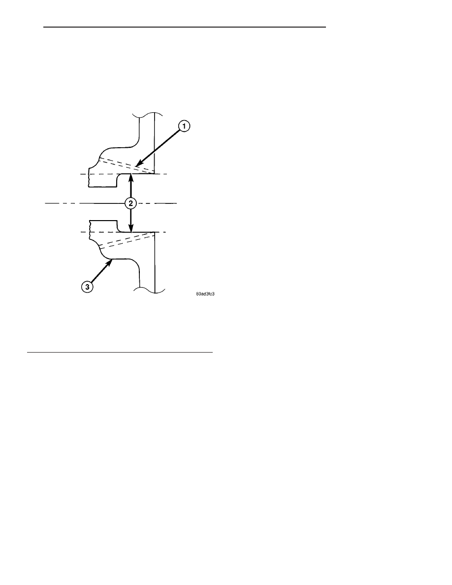
Fig. 151 Manifold Port (Nipple) Repair

1 - BRAKE BOOSTER PORT = 1/4

9

–18 NPT PIPE TAP

1 - LDP/SPEED CONTROL PORT = 1/8

9

–18 NPT PIPE TAP

2 - DRILL BIT = 7/16

9

BRAKE BOOSTER PORT

2 - DRILL BIT = 11/32

9

LDP/SPEED CONTROL PORT

3 - INTAKE MANIFOLD

CS

ENGINE 3.8L

9 - 191

INTAKE MANIFOLD - UPPER (Continued)

Fig. 152 3.8L COMPONENT LOCATION

1 - AIR CLEANER HOUSING

6 - BRAKE BOOSTER VACUUM HOSE

2 - INLET AIR TEMPERATURE SENSOR

7 - ACCELERATOR CABLE

3 - IDLE AIR CONTROL VALVE

8 - CRUISE CONTROL CABLE

4 - PCV HOSE

9 - MANIFOLD ABSOLUTE PRESSURE SENSOR

5 - EGR TUBE

10 - CRANK CASE BREATHER

9 - 192

ENGINE 3.8L

CS

INTAKE MANIFOLD - UPPER (Continued)

INSTALLATION - UPPER INTAKE MANIFOLD

(1) If the following components were removed from

manifold, install and tighten to specifications:

CAUTION: The special screws used for the compos-
ite manifold attached components must be installed
slowly using hand tools only. This requirement is to
prevent the melting of material that causes stripped
threads. If threads become stripped, an oversize
repair screw is available. For more information and
procedure (Refer to 9 - ENGINE/MANIFOLDS/IN-
TAKE MANIFOLD - STANDARD PROCEDURE - MAN-
IFOLD STRIPPED THREAD REPAIR).

• MAP sensor - 1.7 N·m (15 in. lbs.)

• Throttle cable bracket - 5.6 N·m (50 in. lbs.)
(2) Remove covering on lower intake manifold and

clean surfaces.

(3) Inspect manifold gasket condition. Gaskets can

be re-used, if not damaged. Position new gasket in
seal channel and press lightly in-place. Repeat proce-
dure for each gasket position.

(4) Position upper manifold on lower manifold.
(5) Apply Mopar

t Lock & Seal Adhesive (Medium

Strength Threadlocker) to each upper intake mani-
fold bolt. Install and tighten bolts to 12 N·m (105 in.
lbs.) following torque sequence in (Fig. 154).

(6) Connect the MAP sensor electrical connector

(Fig. 155).

(7) Connect the brake booster and cruise control

vacuum hose to intake manifold (Fig. 155).

CAUTION: The special screws used for attaching
the EGR tube to the manifold must be installed
slowly using hand tools only. This requirement is to
prevent the melting of material that causes stripped
threads. If threads become stripped, an oversize
repair screw is available. For more information and
procedure (Refer to 9 - ENGINE/MANIFOLDS/IN-
TAKE MANIFOLD - STANDARD PROCEDURE - MAN-
IFOLD STRIPPED THREAD REPAIR).

(8) Install the EGR tube.

Fig. 153 THROTTLE ASSEMBLY

1 - EGR TUBE
2 - ACCELERATOR CABLE
3 - CRUISE CONTROL CABLE
4 - FUEL INLET
5 - EVAP HOSE
6 - THROTTLE POSITION SENSOR
7 - PCV HOSE
8 - IDLE SPEED CONTROL

Fig. 154 UPPER MANIFOLD TIGHTENING

SEQUENCE

CS

ENGINE 3.8L

9 - 193

INTAKE MANIFOLD - UPPER (Continued)

Fig. 155 3.8L COMPONENT LOCATION

1 - AIR CLEANER HOUSING

6 - BRAKE BOOSTER VACUUM HOSE

2 - INLET AIR TEMPERATURE SENSOR

7 - ACCELERATOR CABLE

3 - IDLE AIR CONTROL VALVE

8 - CRUISE CONTROL CABLE

4 - PCV HOSE

9 - MANIFOLD ABSOLUTE PRESSURE SENSOR

5 - EGR TUBE

10 - CRANK CASE BREATHER

9 - 194

ENGINE 3.8L

CS

INTAKE MANIFOLD - UPPER (Continued)


Content   ..  707  708  709  710   ..