Chrysler Pacifica. Manual - part 525


  Index      Chrysler     Chrysler Pacifica - service repair manual 2005 year


Search            


Content   ..  523  524  525  526   ..


Chrysler Pacifica. Manual - part 525


(8) Turn the ignition switch to the “OFF” position.

Disconnect the motor/module and sunroof switch
electrical connectors. Using an ohmmeter check for
continuity on the “VENT”, “CLOSE” and “OPEN” cir-
cuits between the motor/module and sunroof switch.
Continuity should be present. If OK, (Refer to 8 -
ELECTRICAL/POWER TOP/SWITCH - DIAGNOSIS
AND TESTING) for diagnosis of the sunroof switch.
If not OK, repair the control circuits as necessary.

STANDARD PROCEDURE

SUNROOF MOTOR/MODULE CALIBRATION

CAUTION: THERE IS NO ADJUSTMENT AVAILABLE
FOR A NORMALLY OPERATING SUNROOF. THIS
PROCEDURE IS USED TO SET SUNROOF MOTOR/
MODULE TO SUNROOF ASSEMBLY TIMING.

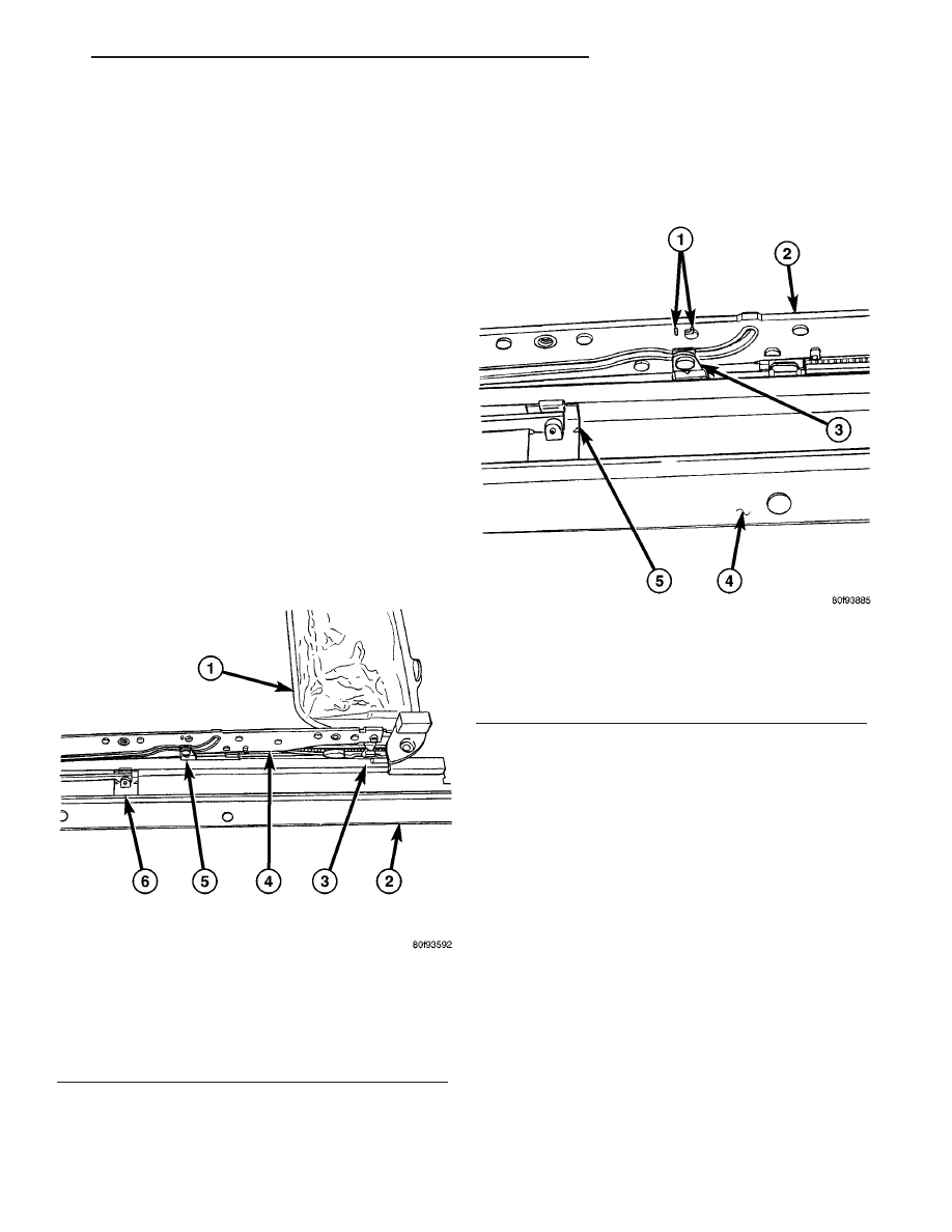
(1) Manually push the sunroof guide assembly to

the full forward position until it is locked into posi-
tion. This is verified by attempting to push the guide
assembly rearward (Fig. 2).

NOTE: The guide rail will be raised above the
U-frame assembly when in the lock position.

(2) Remove the sunroof glass (Refer to 23 - BODY/

SUNROOF/GLASS PANEL - REMOVAL).

(3) Manually move the guide pivot inside the guide

rail cam slot until it is centered between the etched
timing marks on both rails (Fig. 3).

(4) Verify that the white marking is visible in the

new motor/module window. If the mark is not visible,
connect a power source to the motor/module and
cycle the switch until the motor/module is in the
closed position (white mark in window) (Fig. 4).

(5) Install the sunroof motor/module and verify

proper sunroof operation, (Refer to 8 - ELECTRICAL/
POWER TOP/MOTOR - INSTALLATION).

(6) Install the sunroof glass, leaving the retaining

bolts loose.

(7) Install the sunroof assembly into the vehicle

(Refer to 23 - BODY/SUNROOF/MODULE ASSEM-
BLY - INSTALLATION).

(8) Flush the sunroof glass into the vehicle roof

opening and check sunroof glass alignment (Refer to
23 - BODY/SUNROOF/GLASS PANEL - ADJUST-
MENTS).

REMOVAL

(1) Remove the sunroof assembly, (Refer to 23 -

BODY/SUNROOF/MODULE

ASSEMBLY

-

REMOVAL).

Fig. 2 SUNROOF GUIDE LOCK POSITION

1 - SUN SHADE
2 - U - FRAME
3 - U- FRAME SLOT
4 - GUIDE RAIL
5 - GUIDE RAIL PIVIOT
6 - WIND DEFLECTOR

Fig. 3 SUNROOF GUIDE PIVOT

1 - TIMING MARKS
2 - GUIDE RAIL
3 - GUIDE RAIL PIVIOT
4 - U-FRAME
5 - WIND DEFLECTOR

CS

POWER TOP - SUNROOF

8N - 41

MOTOR/MODULE - SUNROOF (Continued)

(2) Remove the sunroof motor/module retaining

bolts and remove the motor/module from the vehicle.

INSTALLATION

CAUTION: THE SUNROOF MOTOR/MODULE MUST
BE TIMED WITH THE SUNROOF ASSEMBLY. FAIL-
URE TO DO SO WILL RESULT IN IMPROPER SUN-
ROOF OPERATION AND POSSIBLE LEAKAGE OR
DAMAGE TO THE ASSEMBLY.

(1) Assure proper sunroof motor/module timing

before installation, (Refer to 8 - ELECTRICAL/
POWER TOP/MOTOR - STANDARD PROCEDURE -
SUNROOF MOTOR/MODULE CALIBRATION).

(2) Position the sunroof motor/module to the sun-

roof assembly and install the retaining bolts. Tighten
sunroof motor/module retaining bolts to 4.2Nm (40
lbs.in.).

(3)

Connect the timed sunroof assembly to a

power source and assure proper operation before
installing the sunroof assembly into the vehicle.

(4) Install the sunroof assembly in the vehicle,

(Refer to 23 - BODY/SUNROOF/MODULE ASSEM-
BLY - INSTALLATION).

SWITCH - SUNROOF

DESCRIPTION

The power sunroof switch is a combination push-

button and rocker switch mounted in the overhead
console, (Fig. 5). The sunroof switch is a direct con-
tact unit that is directly wired to the sunroof motor/
module assembly. The sunroof switch performs the
following functions:

• Power sunroof open

• Power sunroof closed

• Power sunroof vent

OPERATION

The sunroof is electrically operated from two

switches located on the windshield header, rearward
of the map lamp. The “VENT” switch is a push but-
ton type switch and opens the sunroof to the vent
position only. The other switch “OPEN/CLOSED” is a
rocker type switch for opening and closing the sun-
roof. Pressing and releasing the open button once,
the sunroof will express open and the wind deflector
will raise. If the button is pressed a second time the
sunroof will stop in that position. Pressing and hold-
ing the close button will close the sunroof. If the
close button is released the sunroof will stop in that
position.

The switch is grounded at on terminal and receives

a 12 volt signal from the sunroof motor/module on
the remaining three terminals. The switch pulls
down the 12 volt reference voltage from the motor/
module signaling it to perform the desired function.

For complete circuit diagrams, refer to the

appropriate wiring information. The wiring infor-
mation includes wiring diagrams, proper wire and
connector repair procedures, details of wire harness

Fig. 4 SUNROOF MOTOR/MODULE

1 - SUNROOF MOTOR/MODULE TIMING WINDOW
2 - SUNROOF MOTOR/MODULE

Fig. 5 POWER SUNROOF SWITCH

8N - 42

POWER TOP - SUNROOF

CS

MOTOR/MODULE - SUNROOF (Continued)

routing and retention, connector pin-out information
and location views for the various wire harness con-
nectors, splices and grounds.

DIAGNOSIS AND TESTING

SUNROOF SWITCH

For complete circuit diagrams, refer to the appro-

priate wiring information. The wiring information
includes wiring diagrams, proper wire and connector
repair procedures, details of wire harness routing
and retention, connector pin-out information and
location views for the various wire harness connec-
tors, splices and grounds. Perform the following test
prior to switch replacement.

(1) Remove the overhead console, (Refer to 8 -

ELECTRICAL/OVERHEAD

CONSOLE

-

REMOVAL).

(2) Disconnect the power sunroof switch wire har-

ness connector.

(3) With the ignition key in the “RUN” position

check for battery voltage on the “OPEN”, “CLOSE”
and “VENT” circuits of the sunroof switch harness
connector. If OK, go to Step 4. If not OK, inspect the
wiring harness and connectors between the motor/
module and switch for damage and repair as neces-
sary.

(4) With the ignition key in the “OFF” position

check for continuity between the ground circuit of the
sunroof switch harness connector and a known good
ground. Continuity should be present. If OK, go to
Step 5. If not OK, inspect the wiring harness and
connector and repair the ground circuit as necessary.

(5) Using an ohmmeter, test the continuity of the

power sunroof switch (Fig. 6) in each switch position.

Refer to the POWER SUNROOF SWITCH CONTI-
NUITY TABLE. If OK, inspect the wiring harness
and connectors for damage and repair as necessary.
If not OK, replace the power sunroof switch, (Refer to
8

-

ELECTRICAL/POWER

TOP/SWITCH

-

REMOVAL).

POWER SUNROOF SWITCH CONTINUITY

TABLE

SWITCH POSITION

CONTINUITY BETWEEN

PINS

OFF

NO CONTINUITY

SUNROOF OPEN

3 & 1

SUNROOF CLOSED

3 & 4

SUNROOF VENT

3 & 2

REMOVAL

(1) Disconnect and isolate the battery negative

cable.

(2) Separate the overhead console from the head-

liner, by carefully pulling down on the front portion,
toward the windshield, to release the retaining clips
(Fig. 7).

(3) Release the sunroof switch retaining tab, dis-

connect the electrical connector and remove the
switch from the overhead console (Fig. 7).

Fig. 6 SUNROOF SWITCH PINOUT

Fig. 7 OVERHEAD CONSOLE

1 - OVERHEAD CONSOLE
2 - POWER SUNROOF SWITCH
3 - SUNROOF SWITCH RETAINING CLIP (PART OF CONSOLE)
4 - OVERHEAD CONSOLE RETAINING CLIPS

CS

POWER TOP - SUNROOF

8N - 43

SWITCH - SUNROOF (Continued)

INSTALLATION

(1) Position the sunroof switch against the over-

head console and push the switch to properly seat in
retaining clip (Fig. 8).

(2) Install the overhead console assembly, (Refer to

8 - ELECTRICAL/OVERHEAD CONSOLE - INSTAL-
LATION).

(3) Connect the battery negative cable.
(4) Confirm proper sunroof system operation.

Fig. 8 OVERHEAD CONSOLE

1 - OVERHEAD CONSOLE
2 - POWER SUNROOF SWITCH
3 - SUNROOF SWITCH RETAINING CLIP (PART OF CONSOLE)
4 - OVERHEAD CONSOLE RETAINING CLIPS

8N - 44

POWER TOP - SUNROOF

CS

SWITCH - SUNROOF (Continued)


Content   ..  523  524  525  526   ..