Chrysler Pacifica. Manual - part 523
PASSENGER SEAT SWITCH
DESCRIPTION
The passenger seat switch assembly includes up to
three switches ganged together in one compact
switch assembly. The switch is located on the passen-
gers front door trim panel. This seat switch assembly
can provide up to three resistive multiplexed inputs
into the passenger door module. These inputs control
the heated seat and power seat system functions,
depending on how the vehicle is equipped. All inputs
are hardwired resistive mux to the passenger door
module to decode axis direction or seat heat level.
The passenger door module sends out the system
requests over the Programmable Communications
Interface (PCI) data bus circuit. Refer to Passenger
Door Module or Memory Heated Seat Adjustable
Pedal Module in the Electronic Control Modules sec-
tion for additional information on these modules.
The switch assembly is secured to the back of the
front door trim panel (Fig. 4) with clips.
The
switch
assembly
cannot
be
adjusted
or
repaired. If one switch is damaged or faulty, the
entire seat switch assembly must be replaced.
OPERATION
The passenger seat switch has up to three momen-
tary switch buttons. The heated seat switch portion
of the switch is back-lit with Light-Emitting Diodes
(LED) for easy visibility. When any of the switch but-
tons are depressed, a resistance signal is sent to the
Passenger Door Module (PDM) via hard wired con-
nections. The passenger door module then sends the
request to the Memory Heated Seat Adjustable Pedal
Module (MHSAPM) via the PCI data bus circuit. The
MHSAPM is responsible for controlling the 12volt
battery source and ground path to the seat heating
elements or power seat track mounted motors to con-
trol the seat accordingly.
Any seat axis or seat heat inputs can be activated
at the same time (except contradictory inputs). The
passenger door module has two outputs to the seat
switch to indicate heat level (HI/LO). The power seat
system is operational in any ignition switch position.
The heated seat system only operates with the igni-
tion on. See the owner’s manual in the vehicle glove
box for more information on the seat switch functions
and the seat adjusting procedures.
DIAGNOSIS AND TESTING - PASSENGER SEAT
SWITCH
(1) Remove the passenger seat switch, refer to the
following Switch Removal procedure in this section.
(2) Using an ohmmeter, check the appropriate
ground circuit cavity of the power seat switch connec-
tor for continuity to ground. It should be present, If
OK go to Step 3 , If NOT OK repair the open ground
circuit as required.
(3) Using an voltmeter, check the appropriate 12v cir-
cuit cavity of the power seat switch connector for
approx. 12v. It should be present, If OK go to Step 4 , If
NOT OK repair the open voltage supply circuit as
required.
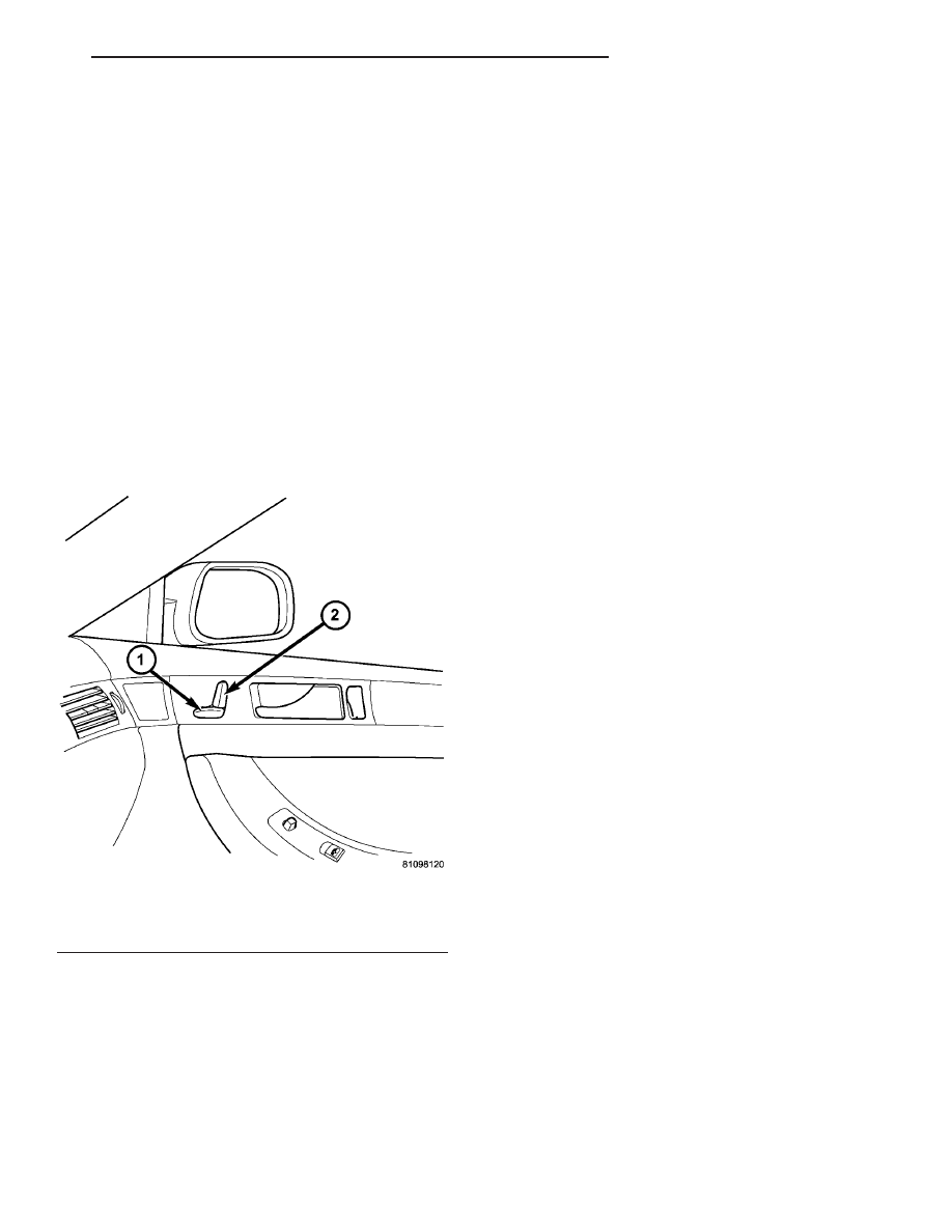
Fig. 4 CS Passenger Seat Switch
1 - Seat Cushion Adjuster
2 - Seat Back Adjuster
CS
POWER SEAT SYSTEM
8N - 33