Chrysler Pacifica. Manual - part 482


  Index      Chrysler     Chrysler Pacifica - service repair manual 2005 year


Search            


Content   ..  480  481  482  483   ..


Chrysler Pacifica. Manual - part 482


• Clutch Plate and/or Seal Replacement

• Valve Body Replacement or Recondition
To perform the Quick Learn Procedure, the follow-

ing conditions must be met:

• The brakes must be applied

• The engine speed must be above 500 rpm

• The throttle angle (TPS) must be less than 3

degrees

• The shift lever position must stay until

prompted to shift to overdrive

• The shift lever position must stay in overdrive

after the Shift to Overdrive prompt until the
DRBIII

t indicates the procedure is complete

• The calculated oil temperature must be above

60° and below 200°

(1) Plug the DRBIII

t scan tool into the diagnostic

connector. The connector is located under the instru-
ment panel.

(2) Go to the Transmission screen.
(3) Go to the Miscellaneous screen.
(4) Select Quick Learn Procedure. Follow the

instructions of the DRBIII

t to perform the Quick

Learn Procedure.

REMOVAL

(1) Disconnect the negative battery cable.
(2) Raise vehicle and support.
(3) Remove the left front wheel.
(4) Remove the left front splash shield.
(5) Unlock and remove the 4 connectors (Fig. 17).
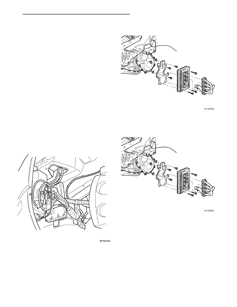
(6) Remove the 3 mounting screws (Fig. 18).
(7) Remove the PCM.

INSTALLATION

(1) Install the PCM.
(2) Install the 3 mounting screws (Fig. 19).
(3) Tighten screws.

NOTE: The PCM connectors are color coded.

Fig. 17 PCM LOCATION

Fig. 18 PCM ASSEMBLY

Fig. 19 PCM ASSEMBLY

CS

ELECTRONIC CONTROL MODULES

8E - 15

POWERTRAIN CONTROL MODULE (Continued)

(4) Install and lock the 4 electrical connectors (Fig.

20).

(5) Install the left front splash shield.
(6) Install the left front wheel.
(7) Lower vehicle.
(8) Connect the negative battery cable.

MEMORY/HEATED SEAT
ADJUSTABLE PEDAL MODULE

DESCRIPTION

A Memory Heated Seat/Adjustable Pedal Module

(MHSAPM) is used on vehicles that are equipped
with the heated seat system option. A Memory Seat/
Adjustable Pedal Module (MSAPM) is used on vehi-
cles that are not equipped with the heated seat
system option. This module contains all the software
and control logic for the front memory/heated and
power seat systems, as well as the adjustable foot
pedal system. The memory heated seat/adjustable
pedal module contains a central processing unit and
interfaces with the Programmable Communications
Interface (PCI) data bus circuit. Refer to the Heated
Seat System 
section for more information on the
heated seat system. Refer to the Power Seat Sys-
tem 
section for more information on the power/mem-
ory seat system.

The module is packaged in a black molded plastic

case which is mounted under the edge of the driver
side front seat cushion. This location makes it some-
what difficult to access because it sits between the
power seat track and the seat cushion frame. Refer

to the following procedure in this section for detailed
removal and installation instructions.

For diagnosis of the MHSAPM or the PCI data

bus, a DRB III

t scan tool and the Diagnostic Proce-

dures

Manual

are

recommended.

The

Memory

Heated Seat/Adjustable Pedal Module cannot be
adjusted or repaired and, if faulty or damaged, it
must be replaced.

OPERATION

The Memory Heated Seat/Adjustable Pedal Module

controls the heated, power and memory seat systems
as well as the adjustable foot pedal system. However
different, these systems share some software inside
the module. Refer to the following text which
explains how the different systems are controlled by
the memory heated seat/adjustable pedal module.

FRONT HEATED SEAT SYSTEM OPERATION

When either of the front heated seat switches are

depressed a resistor multi-plexed signal is sent to the
corresponding door module (Driver or Passenger).
The applicable Door Module then sends a message
via the Programmable Communications Interface
(PCI) data bus network to the Memory Heated Seat
Adjustable Pedal Module (MHSAPM), signaling the
module to energize the heating element for the
selected seat. Light Emitting Diodes (LEDS) in each
switch indicate the level of heat in use. The switch
LEDs are controlled by the applicable Door Module.

The MHSAPM energizes an integral solid-state

relay, which supplies battery current to the seat
heating elements. When high-temperature heating is
selected, the heaters provide a boosted heat level
during the first four minutes of operation after heat-
ing is activated. The heat output then drops to the
normal selected-temperature level. If high-level heat-
ing is selected, the control system will automatically
switch to the low level after two hours of continuous
operation. Operation on the low setting turns off only
when the ignition switch is turned off or the heated
seat switch is pressed a second time indicating an off
command.

MEMORY SEAT SYSTEM OPERATION

Depressing any of the drivers front door trim panel

mounted, memory seat switches sends a hardwired,
resistor multi-plexed signal to the drivers door mod-
ule. The door module then sends a PCI data bus mes-
sage to the Memory Heated Seat/Adjustable Pedal
Module (MHSAPM). The module detects the memory
seat switch status via the PCI data bus circuit and
energizes the appropriate power seat motors. The
programmed software in the MHSAPM allows it to
know the location of the seat track by a resistance
value generated from the seat track mounted poten-

Fig. 20 PCM LOCATION

8E - 16

ELECTRONIC CONTROL MODULES

CS

POWERTRAIN CONTROL MODULE (Continued)

tiometers.

When

the

correct

preset

location

is

achieved the module will de-energize the power seat
track motors. The MHSAPM will prevent the seat
memory recall function from being initiated if the
transmission gear selector lever is not in the Park or
Neutral positions, or if the vehicle is moving. These
inputs are monitored over the PCI data bus circuit.

ADJUSTABLE FOOT PEDAL SYSTEM OPERATION

Depressing the adjustable foot pedal switch sends

a hardwired, resistor multi-plexed signal to the driv-
ers door module. The door module then sends a PCI
data bus message to the Memory Heated Seat/Ad-
justable Pedal Module (MHSAPM). The module
detects the adjustable pedal switch status via the
PCI data bus circuit and energizes the appropriate
foot pedal motor. When the foot pedal switch is
released the module will stop the motor.

Depressing the memory switch will signal the module

to move the pedal assembly to the preprogrammed posi-
tion. The programmed software in the MHSAPM allows
it to know the location of the foot pedal assembly by a
resistance value generated from the pedal assembly
mounted potentiometer. When the correct preset loca-
tion is achieved the module will de-energize the foot
pedal motor. The MHSAPM will prevent the adjustable
foot pedal function from being initiated if the transmis-
sion gear selector lever is not in the Park or Neutral
positions, or if the vehicle is moving. These inputs are
monitored over the PCI data bus circuit also.

DIAGNOSIS AND TESTING - MEMORY HEATED
SEAT ADJUSTABLE PEDAL MODULE

In order to obtain conclusive testing of the memory

heated seat adjustable pedal module, the Program-
mable Communications Interface (PCI) data bus cir-
cuit and any components that provide inputs to the
module must be checked.

The most reliable, efficient, and accurate means to

diagnose the module requires the use of a DRB III

t

scan tool and the Service and Body Diagnostic Proce-
dures Manuals. The DRB III

t scan tool can provide

vital information to the technician trying to find a prob-
lem with the module. Diagnostic logic software is built
into the memory heated seat adjustable pedal module to
help the person trying to locate the problem by the most
efficient means possible. Anytime a problem is sus-
pected, a DRB III

t scan tool should be obtained and

used to retrieve any stored fault codes in the memory
heated seat adjustable pedal module. If diagnostic fault
codes are present in the module, record them on a piece
of paper immediately before proceeding any further.
Then, use these fault codes to identify the problem by
verifying the fault code. Example, If the module records
“DRIVER SEAT HEAT OUTPUT OPEN” fault, locate
the diagnostic procedure for this code in the appropriate

Body Diagnostic Procedures Manual and follow the flow
chart until the specific problem is located and resolved.
Once the problem is corrected, erase the stored fault
code using the DRB III

t scan tool and verify correct

heated seat system operation. If the heated seat system
appears to be functioning correctly, verify that there are
no other stored codes in the module and return the
vehicle to service.

If the fault code could not be verified, such as not

finding anything wrong when following the diagnos-
tic flow chart in the Body Diagnostic Procedures
Manual. This is a good indication that a INTERMIT-
TENT problem may be present. You must than
attempt to find the intermittent problem, such as
moving the heating element within the seat while
testing continuity or wiggling the wire harness’s/elec-
trical connectors under the seat while testing conti-
nuity. Always, eliminate all other potential problems
before attempting to replace the memory heated seat
adjustable pedal module.

For complete circuit wiring diagrams, refer to Wir-

ing.

PRELIMINARY TEST

Before testing the individual components in the

suspect system, check the following:

(1) Using the DRB III

t scan tool, check the mem-

ory heated seat adjustable pedal module (MHSAPM)
for any stored fault codes. Record these codes on
paper for reference and resolve using the appropriate
Body Diagnostic Procedures Manual.

(2) Check the vehicles battery open-circuit voltage

and charging system performance. If the vehicles
electrical system is defective or weak it may not be
suppling sufficient voltage to operate the system in
question.

REMOVAL

(1) Position the drivers seat as far upward and

rearward as possible.

(2) Open hood, disconnect and isolate the negative

battery cable.

(3) Remove the memory heated seat adjustable

pedal module attaching screws.

(4) Disconnect the module electrical connectors.
(5) Remove the module from under drivers seat.

INSTALLATION

(1) Position the memory heated seat adjustable

pedal module under the drivers seat.

(2) Connect the module electrical connectors.
(3) Install the module attaching screws.
(4) Connect the negative battery cable.
(5) Position the drivers seat in its original position.
(6) Verify correct system operation.

CS

ELECTRONIC CONTROL MODULES

8E - 17

MEMORY/HEATED SEAT ADJUSTABLE PEDAL MODULE (Continued)


Content   ..  480  481  482  483   ..