Chrysler Pacifica. Manual - part 478


  Index      Chrysler     Chrysler Pacifica - service repair manual 2005 year


Search            


Content   ..  476  477  478  479   ..


Chrysler Pacifica. Manual - part 478


CLOCK

TABLE OF CONTENTS

page

page

CLOCK

DESCRIPTION

. . . . . . . . . . . . . . . . . . . . . . . . . . 1

OPERATION

. . . . . . . . . . . . . . . . . . . . . . . . . . . . 1

DIAGNOSIS AND TESTING - CLOCK

. . . . . . . . . 2

CLOCK

DESCRIPTION

The Analog Clock is located in the Instrument

Panel Switch Pod within the instrument cluster
bezel, just to the right of the instrument cluster (Fig.
1). It is of analog type and has one adjustment but-
ton that will forward the clocks hand position.

The clock is not serviced separately from the

instrument panel switch pod. If found defective, the
entire switch assembly must be replaced (Refer to 8 -
ELECTRICAL/INSTRUMENT

CLUSTER/INSTRU-

MENT PANEL SWITCH POD - REMOVAL).

OPERATION

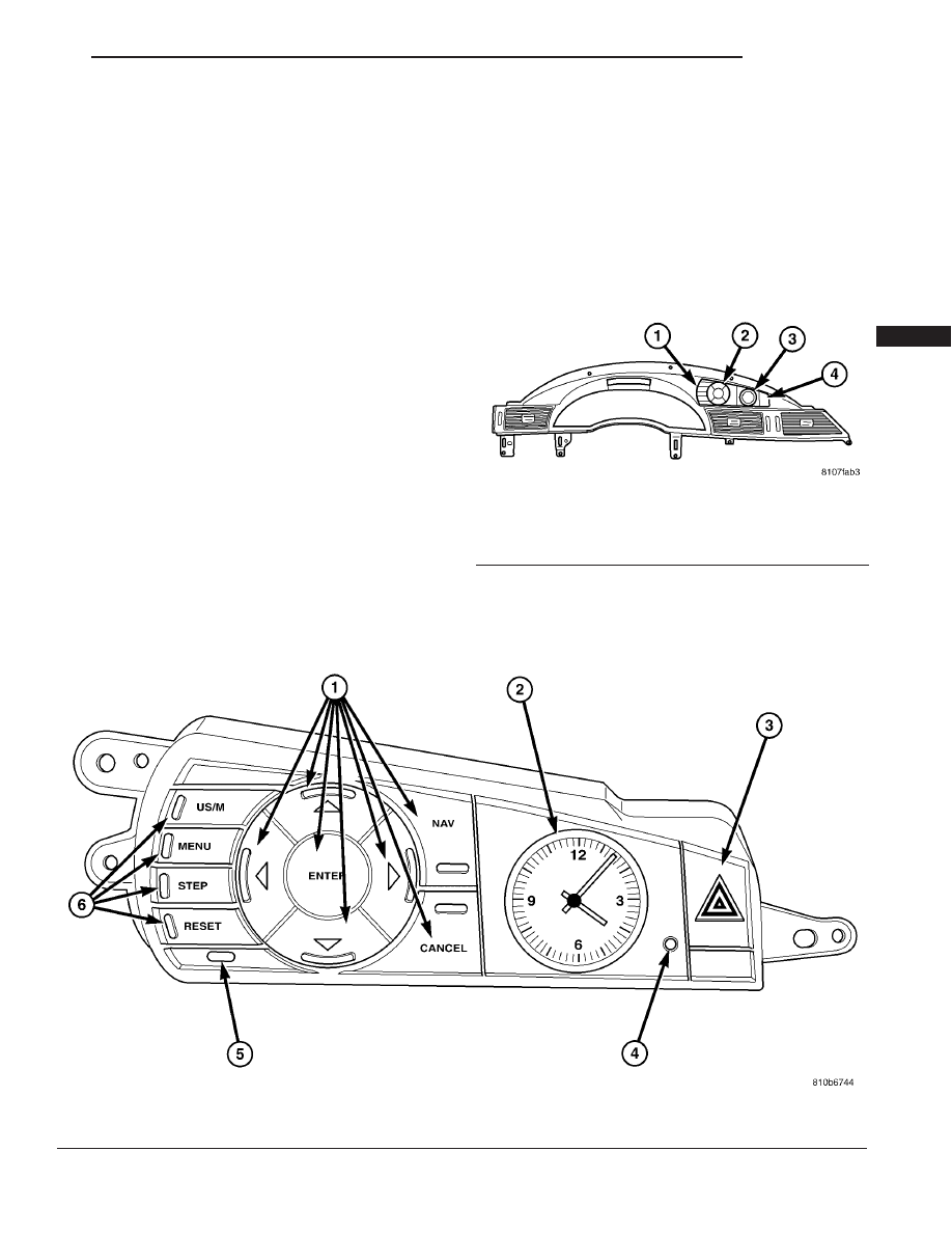
To set the analog clock, at the top center of the

instrument panel, press and hold the button (Fig. 2)
until the setting is correct.

Fig. 2 CLOCK SETTING BUTTON

1 - NAVIGATION CONTROLS

4 - CLOCK SETTING BUTTON

2 - ANALOG CLOCK

5 - VTSS/SKIS LED

3 - HAZARD SWITCH

6 - EVIC CONTROLS

Fig. 1 CLOCK LOCATION

1 - EVIC CONTROLS
2 - NAVIGATION CONTROLS
3 - CLOCK
4 - HAZARD SWITCH

CS

CLOCK

8C - 1

DIAGNOSIS AND TESTING - CLOCK

Refer to Wiring for the appropriate wiring informa-

tion and connector views. Check for 12v battery
power and ground at the instrument panel connector
end of the instrument panel switch pod. If both are
present, replace instrument panel switch pod (Refer
to 8 - ELECTRICAL/INSTRUMENT CLUSTER/IN-
STRUMENT PANEL SWITCH POD - REMOVAL). If
one or both are not present, repair short/open wire.

8C - 2

CLOCK

CS

CLOCK (Continued)

ELECTRONIC CONTROL MODULES

TABLE OF CONTENTS

page

page

BODY CONTROL MODULE

DESCRIPTION

. . . . . . . . . . . . . . . . . . . . . . . . . . 1

OPERATION

. . . . . . . . . . . . . . . . . . . . . . . . . . . . 1

REMOVAL

. . . . . . . . . . . . . . . . . . . . . . . . . . . . . 2

INSTALLATION

. . . . . . . . . . . . . . . . . . . . . . . . . . 3

COMMUNICATION

DESCRIPTION

. . . . . . . . . . . . . . . . . . . . . . . . . . 3

OPERATION

. . . . . . . . . . . . . . . . . . . . . . . . . . . . 3

ANTILOCK BRAKE MODULE (MK25E)

DESCRIPTION

. . . . . . . . . . . . . . . . . . . . . . . . . . 4

OPERATION

. . . . . . . . . . . . . . . . . . . . . . . . . . . . 4

REMOVAL

. . . . . . . . . . . . . . . . . . . . . . . . . . . . . 5

INSTALLATION

. . . . . . . . . . . . . . . . . . . . . . . . . . 6

CONTROLLER ANTILOCK BRAKE (MK25)

DESCRIPTION

. . . . . . . . . . . . . . . . . . . . . . . . . . 7

OPERATION

. . . . . . . . . . . . . . . . . . . . . . . . . . . . 7

REMOVAL

. . . . . . . . . . . . . . . . . . . . . . . . . . . . . 8

INSTALLATION

. . . . . . . . . . . . . . . . . . . . . . . . . . 9

DOOR MODULE

DESCRIPTION

. . . . . . . . . . . . . . . . . . . . . . . . . . 9

OPERATION

. . . . . . . . . . . . . . . . . . . . . . . . . . . . 9

DIAGNOSIS AND TESTING - DOOR MODULE

. 10

REMOVAL

. . . . . . . . . . . . . . . . . . . . . . . . . . . . . 10

INSTALLATION

. . . . . . . . . . . . . . . . . . . . . . . . . 10

POWERTRAIN CONTROL MODULE

DESCRIPTION

DESCRIPTION

. . . . . . . . . . . . . . . . . . . . . . . . 10

DATA BUS COMMUNICATION RECEIVE -

PCM INPUT . . . . . . . . . . . . . . . . . . . . . . . . . . 14

PCM GROUND

. . . . . . . . . . . . . . . . . . . . . . . 14

OPERATION

5 VOLT SUPPLY - PCM OUTPUT

. . . . . . . . . 14

STANDARD PROCEDURE

STANDARD PROCEDURE - OBTAINING

DIAGNOSTIC TROUBLE CODES . . . . . . . . . . 14

STANDARD PROCEDURE - PINION

FACTOR SETTING . . . . . . . . . . . . . . . . . . . . . 14

STANDARD PROCEDURE - QUICK LEARN

PROCEDURE . . . . . . . . . . . . . . . . . . . . . . . . 14

REMOVAL

. . . . . . . . . . . . . . . . . . . . . . . . . . . . . 15

INSTALLATION

. . . . . . . . . . . . . . . . . . . . . . . . . 15

MEMORY/HEATED SEAT ADJUSTABLE PEDAL

MODULE
DESCRIPTION

. . . . . . . . . . . . . . . . . . . . . . . . . 16

OPERATION

. . . . . . . . . . . . . . . . . . . . . . . . . . . 16

DIAGNOSIS AND TESTING - MEMORY

HEATED SEAT ADJUSTABLE PEDAL
MODULE

. . . . . . . . . . . . . . . . . . . . . . . . . . . . 17

REMOVAL

. . . . . . . . . . . . . . . . . . . . . . . . . . . . . 17

INSTALLATION

. . . . . . . . . . . . . . . . . . . . . . . . . 17

BODY CONTROL MODULE

DESCRIPTION

CAUTION: Do not swap BCM’s between vehicles or
with BCM’s off the shelf.

The Body Control Module (BCM) is located on the

bulkhead left side, underneath the instrument panel
(Fig. 1). The BCM utilizes integrated circuitry and
information carried on the Programmable Communi-
cations Interface (PCI) data bus network along with
many hard wired inputs to monitor many sensor and
switch inputs throughout the vehicle. In response to
those inputs, the internal circuitry and programming
of the BCM allow it to control and integrate many
electronic functions and features of the vehicle
through both hard wired outputs and the transmis-
sion of electronic message outputs to other electronic
modules in the vehicle over the PCI data bus.

OPERATION

The Body Control Module (BCM) is operational

when supplied with 12v battery power. The BCM
controls various vehicle functions. It also supplies
information to the instrument cluster to provide
visual and audible information to the vehicle occu-
pants. To provide and receive information, the mod-
ule

interfaces

with

the

vehicle’s

Programmable

Communication Interface (PCI) data bus network.
This network consists of the:

• Integrated Power Module (IPM) - which

incorporates the Power Distribution Center (PDC)
and the Front Control Module (FCM) into one assem-
bly.

• Next Generation Controller (NGC) - which

incorporates the Powertrain Control Module (PCM)
and the Transmission Control Module (TCM) into one
module.

• Instrument Cluster (IC)

CS

ELECTRONIC CONTROL MODULES

8E - 1

• Electronic

Vehicle

Information

Center

(EVIC)

• Occupant Restraint Controller (ORC)

• Compass/Mini-Trip Computer (CMTC)

• Overhead Console

• Controller Antilock Brake (CAB)

• Automatic Temperature Control Module

(ATC)

• Power Liftgate Module (PLGM)

• Audio system

• Memory/Heated Seat Adjustable Pedal Mod-

ule

• Sentry

Key

Remote

Entry

Module

(SKREEM) - which performs the functions of the
previous two modules - Remote Keyless Entry (RKE)
and Sentry Key Immobilizer Module (SKIM).

• Driver Door Module (DDM) and the Passen-

ger Door Module (PDM)

The BCM provides:
• A battery protection feature. - The BCM will

send a message to the IPM to turn off all exterior
lamps after 3 minutes and all interior lamps after 15
minutes after the ignition is turned off, if they are
not turned off by the driver.

• Compass/Minitrip support.

• Interior lighting (courtesy/reading lamps).

• Diagnostic reporting.

• Electronic liftgate release (with power door

locks).

• Exterior lighting.

• Headlamp time delay (with/without auto head-

lamps).

• Automatic headlamps (with electrochromatic

mirror).

• Illuminated entry.

• A fade to off feature. - This feature dims the

interior lighting (courtesy lamps) gradually if the
BCM does not receive any new input that would
cause the interior lamps to remain on.

• Pulse Width Modulated (PWM) instrument

panel dimming.

• Power liftgate switch input. - The BCM has 1

Liftgate switch input located in the overhead console.

• All stalk switch inputs including wipers and

light switches.

• Seat belt position input, indicating a buckled or

unbuckled seat belt.

• Turn signal operation.

• Fuel Level inputs.

• Monitors rear-door ajar switches, liftgate ajar

switches,

multi-function

switches,

multi-function

headlight switch, ignition switch, PCI Bus, and diag-
nostic tool. Based on input from these components,
the BCM will send requests over the PCI Bus to have
the Instrument Cluster perform various chime oper-
ations.

The BCM has internal diagnostic capabilities that

assist in diagnosing the vehicle’s body system. When
an

9Open9 or a 9Short9 circuit exists, the DRBIIIt

scan tool can read the stored BCM Diagnostic Trou-
ble Codes (DTC’s). The DTC’s are very descriptive in
identifying the appropriate feature that has faulted.

Refer to the appropriate Body Diagnostic Proce-

dures manual for Diagnosis and Testing.

REMOVAL

(1) Disconnect and isolate the battery negative

cable.

(2) Remove the lower instrument panel silencer.
(3) Remove the knee blocker airbag (Refer to 8 -

ELECTRICAL/RESTRAINTS/KNEE BLOCKER AIR-
BAG - REMOVAL).

(4) Unclip the 72-way bulkhead connector from the

Body Control Module (BCM) mounting assembly.

(5) Move bulkhead wiring aside.
(6) Disconnect the five wire connectors from the

BCM.

(7) Remove the four screws holding the BCM to

the bulkhead (Fig. 2).

(8) Remove the BCM from the mounting bracket.

Fig. 1 BCM LOCATION

1 - BODY CONTROL MODULE
2 - LOWER STEERING SHAFT
3 - REINFORCEMENT BRACKET

8E - 2

ELECTRONIC CONTROL MODULES

CS

BODY CONTROL MODULE (Continued)


Content   ..  476  477  478  479   ..