Chrysler Pacifica. Manual - part 468


  Index      Chrysler     Chrysler Pacifica - service repair manual 2005 year


Search            


Content   ..  466  467  468  469   ..


Chrysler Pacifica. Manual - part 468


(4) Connect heater and radiator hoses and install

hose clamps.

(5) Connect electrical connectors to engine oil and

power steering pressure switches.

(6) Lower vehicle and connect negative cable to

remote jumper terminal.

(7) Refill cooling system (Refer to 7 - COOLING -

STANDARD PROCEDURE).

(8) Connect negative cable to remote jumper termi-

nal.

HEATER SUPPLY TUBE

REMOVAL

WARNING: DO NOT REMOVE PRESSURE CAP
WITH

SYSTEM

HOT

AND

UNDER

PRESSURE

BECAUSE SERIOUS BURNS FROM COOLANT CAN
OCCUR.

(1) Drain cooling system. (Refer to 7 - COOLING -

STANDARD PROCEDURE).

(2) Remove

upper

and

lower

intake

manifold

(Refer to 9 - ENGINE/MANIFOLDS/INTAKE MANI-
FOLD - REMOVAL).

(3) Position lower intake manifold upside down on

bench and remove the tube retaining bolt (Fig. 7).

(4) Remove tube from manifold and discard O-ring.

INSTALLATION

(1) Clean heater tube sealing surfaces.
(2) Inspect heater tube O-ring. Replace as neces-

sary.

(3) Lubricate O-ring with a silicone type grease

such as Mopar

t Dielectric Grease (Fig. 7).

(4) Install O-ring on heater tube.
(5) Install heater tube on manifold.
(6) Install retaining bolts and tighten to 12 N·m

(105 in. lbs.).

(7) Install lower and upper intake manifolds (Refer

to 9 - ENGINE/MANIFOLDS/INTAKE MANIFOLD -
INSTALLATION).

(8) Refill cooling system (Refer to 7 - COOLING -

STANDARD PROCEDURE).

Fig. 6 Thermostat and Housing - 3.5L Engines

1 - THERMOSTAT HOUSING/COOLANT INLET
2 - THERMOSTAT
3 - GASKET

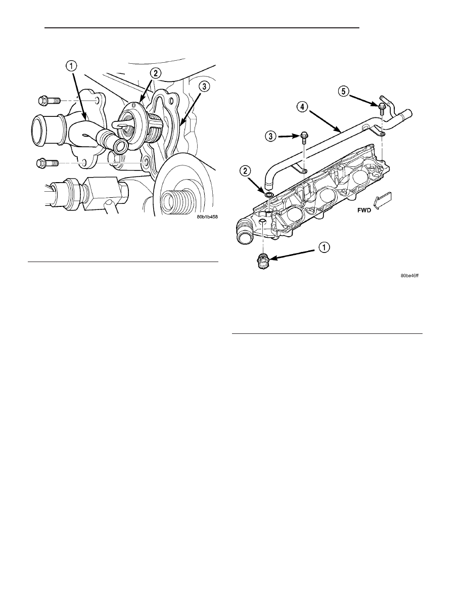
Fig. 7 Heater Supply Tube - 3.5L

1 - COOLANT TEMPERATURE SENSOR
2 - O-RING
3 - BOLT
4 - HEATER SUPPLY TUBE
5 - BOLT

CS

ENGINE

7 - 19

ENGINE COOLANT THERMOSTAT (Continued)

HOSE CLAMPS

DESCRIPTION

The cooling system utilizes both worm drive and

spring type hose clamps. If a spring type clamp
replacement is necessary, replace with the original
Mopar

t equipment spring type clamp. To identify

size of spring hose clamps, the size in millimeters
has been stamped on each clamp (Fig. 8).

OPERATION

The worm type hose clamp uses a specified torque

value to maintain proper tension on a hose connection.

The spring type hose clamp applies constant ten-

sion on a hose connection. To remove a spring type
hose clamp, use Special Tool 6094 or equivalent, con-
stant tension clamp pliers (Fig. 9) to compress the
hose clamp.

RADIATOR

REMOVAL

(1) Disconnect negative cable from battery.
(2) Discardge the A/C system (Refer to 24 - HEAT-

ING & AIR CONDITIONING/PLUMBING/REFRIG-
ERANT - STANDARD PROCEDURE)

(3) Remove the fron fascia (Refer to 13 - FRAME

&

BUMPERS/BUMPERS/FRONT

FASCIA

-

REMOVAL).

WARNING:

DO

NOT

REMOVE

THE

CYLINDER

BLOCK PLUG OR THE RADIATOR DRAINCOCK
WITH THE SYSTEM HOT AND UNDER PRESSURE
BECAUSE SERIOUS BURNS FROM COOLANT CAN
OCCUR.

(4) Drain the cooling system. (Refer to 7 - COOL-

ING - STANDARD PROCEDURE).

(5) Disconnect the radiator fan electrical connectors.
(6) Disconnect coolant reserve/recovery hose.
(7) Remove A/C lines (Refer to 24 - HEATING &

AIR

CONDITIONING/PLUMBING/A/C

CON-

DENSER - REMOVAL).

(8) Remove

the

auxiliary

transmission

cooler

hoses.

(9) Remove the pushpins and the upper radiator

seal.

(10) Remove the pushpins and the LH and RH

radiator seal (Fig. 10).

Fig. 8 Spring Clamp Size Location

1 - SPRING CLAMP SIZE LOCATION

Fig. 9 Hose Clamp Tool

1 - HOSE CLAMP TOOL 6094
2 - HOSE CLAMP

Fig. 10 Radiator Seals

1 - RH RADIATOR SEAL
2. - PUSHPIN
3 - UPPER RADIATOR SEAL

7 - 20

ENGINE

CS

(11) Remove the A/C condenser side brackets to

radiator attaching screws (Fig. 12). Separate the con-
denser from the radiator by lifting upward to disen-
gage

from

lower

mounts

(Fig.

12).

Allow

the

condenser to rest in front of radiator.

(12) Remove the upper and lower radiator hoses.
(13) Radiator can now be lifted free from engine

compartment. Care should be taken not to dam-
age radiator cooling fins or water tubes during
removal. (Fig. 11)

(14) Remove the auxiliary transmission from the

radiator module.

(15) Remove the cooling fan assembly from the

radiator module.

INSTALLATION

(1) Install A/C condenser, (if removed) (Refer to 24

- HEATING & AIR CONDITIONING/PLUMBING/
A/C CONDENSER - INSTALLATION).

(2) Install radiator fan assemble, if removed (Refer

to

7

-

COOLING/ENGINE/RADIATOR

FAN

-

INSTALLATION).

(3) Install

auxiliary

transmission

cooler,

if

removed.

(4) Slide radiator down into position. Seat the

radiator with the rubber isolators into the mounting
holes provided, with a 10 lbs. force.

(5) Install mounting screws.
(6) Connect the cooling fan electrical connector.
(7) Install the radiator upper and lower hoses
(8) In the LH and RH radiator seals.
(9) Install the upper radiator seal.
(10) Install the auxiliary transmission coole hoses.
(11) Connect the coolant reserve/recovery hose.
(12) Install the front fascia (Refer to 13 - FRAME

& BUMPERS/BUMPERS/FRONT FASCIA - INSTAL-
LATION).

(13) Fill the cooling system. (Refer to 7 - COOL-

ING - STANDARD PROCEDURE)

(14) Connect negative cable to battery.

Fig. 11 Radiator Module

1 - RADIATOR MODULE
2 - AUXILIARY TRANSMISSION COOLER HOSES
2 - AUXILIARY TRANSMISSION COOLER

Fig. 12 A/C CONDENSER TO RADIATOR

1 - SCREW - A/C CONDENSER SIDE BRACKET TO RADIATOR
2 - LOWER MOUNT
3 - A/C CONDENSER

CS

ENGINE

7 - 21

RADIATOR (Continued)

RADIATOR DRAINCOCK

REMOVAL

WARNING:

DO

NOT

REMOVE

THE

CYLINDER

BLOCK PLUG OR THE RADIATOR DRAINCOCK
WITH THE SYSTEM HOT AND UNDER PRESSURE
BECAUSE SERIOUS BURNS FROM COOLANT CAN
OCCUR.

CAUTION: Use of pliers on draincock is not recom-
mended. Damage may occur to part. Draincock
should not be removed unless leakage is observed.

(1) Drain the cooling system (Refer to 7 - COOL-

ING - STANDARD PROCEDURE).

(2) Turn the draincock stem counterclockwise 180

degrees to the 9:00 o’clock position.

(3) With the stem at the 9:00 o’clock position, pull

the draincock assembly from the radiator tank (Fig.
13).

INSTALLATION

(1) Inspect the draincock body and O-ring for dam-

age. Replace as necessary.

(2) Position the draincock assembly horizontally to

the tank opening with the manufactures identifica-
tion mark facing down.

(3) Push the draincock assembly into the tank

opening while rotating clockwise until it snaps into
place.

(4) Close the draincock stem by turning clockwise

until it stops at the horizontal position.

(5) Fill the cooling system (Refer to 7 - COOLING

- STANDARD PROCEDURE).

PRESSURE CAP

DESCRIPTION

The cooling system pressure cap is located on the

collant pressure container. The cap construction
includes; stainless steel swivel top, rubber seals, and
retainer, main spring, and a spring loaded valve (Fig.
14).

OPERATION

The cooling system is equipped with a pressure cap

that releases excessive pressure; maintaining a range
of 97-124 kPa (14-18 psi).

The cooling system will operate at higher than

atmospheric pressure. The higher pressure raises the
coolant boiling point thus, allowing increased radia-
tor cooling capacity.

There is also a vent valve in the center of the cap.

This valve also opens when coolant is cooling and
contracting, allowing the coolant to return to cooling
system from coolant reserve system tank by vacuum
through a connecting hose. If valve is stuck shut,
or the coolant recovery hose is pinched, the
radiator hoses will be collapsed on cool down.
Clean the vent valve (Fig. 14) and inspect cool-
ant recovery hose routing, to ensure proper
sealing when boiling point is reached.

The gasket in the cap seals the filler neck, so that

vacuum can be maintained, allowing coolant to be
drawn back into the radiator from the reserve tank.
If the gasket is dirty or damaged, a vacuum
may not be achieved, resulting is loss of coolant
and eventual overheating due to low coolant
level in radiator and engine.

Fig. 13 Draincock

1 - DRAINCOCK ASSEMBLY

Fig. 14 Cooling System Pressure Cap Filler Neck

1 - OVERFLOW NIPPLE
2 - MAIN SPRING
3 - GASKET RETAINER
4 - STAINLESS-STEEL SWIVEL TOP
5 - RUBBER SEALS
6 - VENT VALVE
7 - COOLANT PRESSURE CONTAINER
8 - FILLER NECK

7 - 22

ENGINE

CS


Content   ..  466  467  468  469   ..