Chrysler Pacifica. Manual - part 423


  Index      Chrysler     Chrysler Pacifica - service repair manual 2005 year


Search            


Content   ..  421  422  423  424   ..


Chrysler Pacifica. Manual - part 423


tap with a hammer if necessary) to top of Installer
until seal boot is pressed squarely down against top
surface of lower control arm.

(4) Wipe any grease off ball joint stem using a

clean shop towel with Mopar

t Brake Parts Cleaner

applied to it.

CAUTION: Do not attempt to install a normal grease
zirc in ball joint in an effort to lubricate joint
through zirc fitting.

(5) Install steering knuckle on vehicle. (Refer to 2 -

SUSPENSION/FRONT/KNUCKLE

-

INSTALLA-

TION)

LOWER CONTROL ARM

REMOVAL

(1) Raise and support vehicle. (Refer to LUBRICA-

TION & MAINTENANCE/HOISTING - STANDARD
PROCEDURE)

(2) Remove wheel and tire assembly.
(3) Remove steering knuckle. (Refer to 2 - SUS-

PENSION/FRONT/KNUCKLE - REMOVAL)

(4) Remove bolts and nuts (with flags if equipped)

attaching lower control arm to engine cradle (Fig.
17).

(5) Remove lower control arm.

INSPECTION

Inspect lower control arm for signs of damage from

contact with the ground or road debris. If lower con-
trol arm shows any sign of damage, inspect lower
control arm for distortion. Do not attempt to repair
or straighten a broken or bent lower control arm. If
damaged, the lower control arm is serviced only as a
complete assembly.

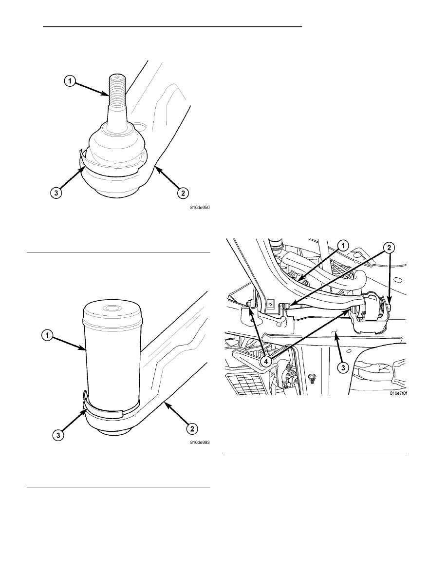
Fig. 15 Ball Joint Seal Boot Installed Position

1 - BALL JOINT STUD
2 - LOWER CONTROL ARM
3 - SEAL BOOT SHIELD

Fig. 16 Installer Positioned On Ball Joint Seal Boot

1 - INSTALLER 6758
2 - LOWER CONTROL ARM
3 - SEAL BOOT SHIELD

Fig. 17 Control Arm Mounting Bolts At Engine

Cradle

1 - LOWER CONTROL ARM
2 - MOUNTING BOLTS
3 - ENGINE CRADLE
4 - FLAG NUTS

CS

FRONT SUSPENSION

2 - 9

LOWER BALL JOINT SEAL BOOT (Continued)

Inspect both lower control arm isolator bushings

for severe deterioration, and replace as required. If a
bushing

fails,

the

lower

control

arm

must

be

replaced.

Inspect and test the ball joint per the procedure

listed in Lower Ball Joint. (Refer to 2 - SUSPEN-
SION/FRONT/LOWER BALL JOINT - DIAGNOSIS
AND TESTING)

INSTALLATION

(1) Position lower control arm into brackets on

engine cradle (Fig. 17).

NOTE: If equipped with flag nuts, when installing
lower control arm-to-cradle REAR mounting bolts,
ensure flags on mounting nuts are positioned as
follows to avoid contact with lower control arm
(LCA) once bolts are tightened:

Left LCA rear flag nut – flag positioned upward

(above LCA)

Right LCA rear flag nut – flag positioned down-

ward (below LCA)
Flags on front mounting nuts are self explanatory.

(2) Install NEW bolts attaching lower control arm

bushings to engine cradle (Fig. 17). Install bolts from
rear as shown. Thread bolts into properly positioned
nuts (with flags if equipped. See preceding note).
Do not tighten bolts at this time.

(3) Install steering knuckle, brake rotor and cali-

per. (Refer to 2 - SUSPENSION/FRONT/KNUCKLE -
INSTALLATION)

(4) Install tire and wheel assembly (Refer to 22 -

TIRES/WHEELS - INSTALLATION). Tighten wheel
mounting nuts to 135 N·m (100 ft. lbs.) torque.

(5) Lower vehicle.
(6) Position vehicle on alignment rack/drive-on

hoist. Raise vehicle as necessary to access mounting
bolts.

(7) Tighten lower control arm frame mounting

bolts to 163 N·m (120 ft. lbs.) torque.

(8) Perform wheel alignment. (Refer to 2 - SUS-

PENSION/WHEEL

ALIGNMENT

-

STANDARD

PROCEDURE)

STABILIZER BAR

REMOVAL

(1) Raise and support vehicle. (Refer to LUBRICA-

TION & MAINTENANCE/HOISTING - STANDARD
PROCEDURE)

(2) Remove both front wheel and tire assemblies.
(3) Remove nut attaching outer tie rod to steering

knuckle by holding rod end stud stationary while
loosening and removing nut with a wrench.

(4) Remove tie rod end from steering knuckle

using Remover, Special Tool C-3894-A (Fig. 18).

CAUTION: When removing nut from stud of stabi-
lizer bar link, do not allow stud to rotate in it’s
socket. Hold stud from rotating by placing an open-
end wrench on flat machined into stud (Fig. 19).

(5) Remove stabilizer bar links from each end of

stabilizer bar (Fig. 19). To do so, place an open-end
wrench on flat machined into link’s mounting stud,
then remove nut while holding wrench in place. Push
each stud out of hole in stabilizer bar.

(6) Remove stabilizer bar cushion retainers as fol-

lows (Fig. 20):

(a) Loosen front bolts at each retainer (Do not

remove). An open-end wrench works best, but a
socket may be used if correct length extension is
used.

(b) Remove rear bolts at each retainer.
(c) Slide stabilizer toward rear of vehicle.
(d) Remove both retainers and cushions from

bar.
(7) Remove stabilizer bar out through right wheel

opening by carefully rotating bar up-and-down, and
back-and-forth as necessary.

INSPECTION

Inspect for broken or distorted stabilizer bar bush-

ings (cushions), bushing retainers, and worn or dam-
aged stabilizer bar links. Also inspect retainers for
damaged heat shields and missing or damaged rivets.

Fig. 18 Using C-3894-A To Release Tie Rod

1 - PULLER C-3894-A
2 - OUTER TIE ROD
3 - STEERING KNUCKLE
4 - TIE ROD STUD

2 - 10

FRONT SUSPENSION

CS

LOWER CONTROL ARM (Continued)

INSTALLATION

NOTE: When installing stabilizer bar, make sure it
installed so that bar curves upward at ends to meet
stabilizer links (Fig. 21).

(1) Insert stabilizer bar over cradle through right

front wheel opening in reverse direction it was
removed in. Ensure bar gets routed in front of
brake tubes on cradle.

NOTE: When installing cushion retainers, make
sure shielded retainer is installed on right side with
shield pointing forward.

(2) Install cushions on stabilizer bar utilizing slits

in cushions. Install each cushion so its slit faces for-
ward and flat side is positioned toward cradle once
installed (Fig. 21).

(3) Install

retainers

on

cushions.

Make

sure

retainer with shield is placed over right cushion with
shield facing forward.

(4) Slide stabilizer bar forward engaging slotted

holes on retainers with retainer mounting bolts in
cradle.

(5) Install rear retainer mounting bolts.
(6) Tighten all four retainer mounting bolts to 54

N·m (40 ft. lbs.) torque (Fig. 20).

NOTE: Once retainer bolts are tightened, make sure
heat shields are not bent or mis-positioned.

(7) Install each stabilizer bar link mounting stud

through hole in each end of stabilizer bar.

CAUTION: When installing nut on mounting stud of
stabilizer bar link, do not allow stud to rotate in it’s
socket. Hold stud stationary by placing an open-
end wrench on flat machined into stud (Fig. 19).

Fig. 19 Stabilizer Bar Link To Stabilizer Bar

Attachment

1 - RATCHET
2 - WRENCH
3 - STRUT
4 - STABILIZER BAR LINK
5 - NUT
6 - STABILIZER BAR

Fig. 20 Accessing Stabilizer Bar Cushion Retainer

Bolts (Right shown - Left Typical)

1 - RATCHET/TORQUE WRENCH WITH EXTENSION AND
SOCKET
2 - POWER STEERING GEAR BOOT
3 - CUSHION RETAINER

Fig. 21 Front Stabilizer Bar

1 - SHIELD (MOUNTED TO RIGHT RETAINER)
2 - STABILIZER BAR
3 - CUSHIONS
4 - RETAINERS

CS

FRONT SUSPENSION

2 - 11

STABILIZER BAR (Continued)

(8) Hand-thread nut on end of each stabilizer bar

link studs. Then hold studs from turning by placing
an open-end wrench on flat machined into each link’s
mounting stud, then tighten each nut (Fig. 19).
Tighten each nut to 88 N·m (65 ft. lbs.) torque.

(9) Install outer tie rods to steering knuckles.

Start NEW nut onto stud of each outer tie rod. Start
nut onto tie rod stud. While holding stud stationary
using a socket, tighten nut using a wrench. Using a
crowfoot wrench on a torque wrench, tighten nut to
47 N·m (35 ft. lbs.) torque. Then, tighten nut an
additional 1/2 (180°) turn after that torque is met.

(10) Install tire and wheel assembly (Refer to 22 -

TIRES/WHEELS - INSTALLATION). Tighten wheel
mounting nuts to 135 N·m (100 ft. lbs.) torque.

(11) Lower vehicle.

STRUT ASSEMBLY

DESCRIPTION

A Macpherson type strut assembly is used in place

of a conventional front suspension’s upper control
arm and upper ball joint. The bottom of the strut
mounts directly to the steering knuckle using two
bolts and nuts going through the strut clevis bracket
and steering knuckle. The top of the strut mounts
directly to the strut tower of the vehicle using the
threaded studs on the strut assemblies upper mount.

The strut assembly includes the components listed

in the figure (Fig. 22).

Each component is serviced by removing the strut

assembly from the vehicle and disassembling it.

Left and right springs must not be interchanged.

Coil springs are rated separately for each corner or
side of the vehicle depending on optional equipment
and type of vehicle service. If the coil springs require
replacement, be sure that the springs are replaced
with springs meeting the correct load rating and
spring rate for the vehicle and its specific options.

Fig. 22 Strut Assembly

1 - NUT
2 - UPPER MOUNT
3 - PIVOT BEARING
4 - UPPER SPRING SEAT
5 - UPPER SPRING ISOLATOR

6 - COIL SPRING
7 - DUST SHIELD
8 - JOUNCE BUMPER
9 - LOWER SPRING ISOLATOR
10 - STRUT (DAMPER)

2 - 12

FRONT SUSPENSION

CS

STABILIZER BAR (Continued)


Content   ..  421  422  423  424   ..